Slurry bed reactor
A technology of reactor and slurry bed, which is applied in the field of slurry bed reactor, can solve the problems of unfavorable slurry flow, thermal mass transmission, and unsmooth heat exchange plate, so as to improve reaction efficiency and heat exchange efficiency, and improve Cooling and cooling effect, effect of enhancing flow effect
- Summary
- Abstract
- Description
- Claims
- Application Information
AI Technical Summary
Problems solved by technology
Method used
Image
Examples
Embodiment 1
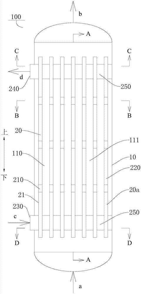
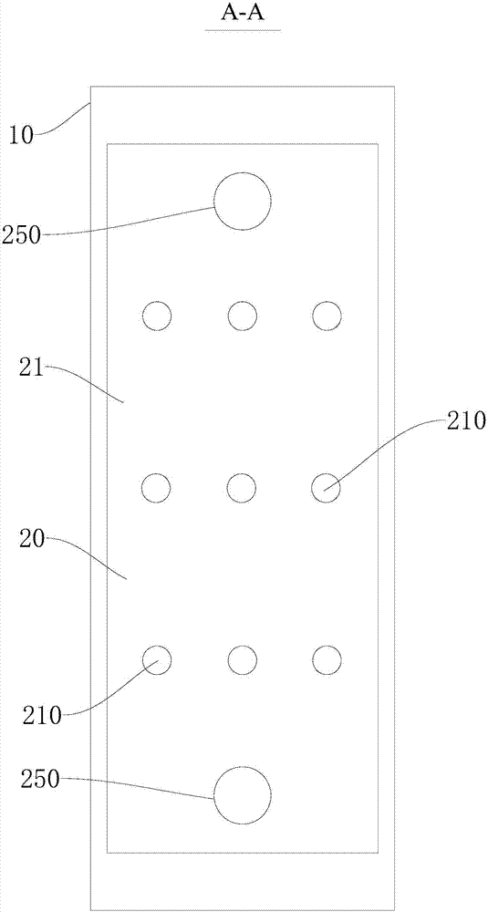
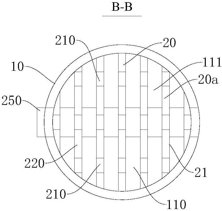
[0061] Such as Figure 1-Figure 5 As shown, the slurry bed reactor 100 includes: a shell 10 and a heat exchanger 20 .
[0062] Among them, such as figure 1 and figure 2 As shown, the slurry bed reactor 100 has a shell 10 defining a reaction chamber 110 . The height of the reaction chamber 110 (ie figure 1 and figure 2 The height in the vertical direction shown in ) is 7000mm, and the inner diameter is 600mm. A slurry may be passed into the reaction chamber 110, and the slurry may include a solvent and a catalyst. The reaction raw material gas a may pass into the reaction chamber 110 from the bottom of the slurry bed reactor 100 and be dissolved in a solvent. At a suitable temperature, the reaction raw material gas a can react to generate the corresponding reaction product b under the action of the catalyst. For example, taking the hydrogenation of acetylene to produce ethylene as an example, the solvent in the slurry may have high selective solubility for acetylene an...
Embodiment 2
[0070] Such as Figure 6-Figure 10 As shown, the difference from Embodiment 1 is that in this embodiment, the heat exchanger 20 includes three annular sub-heat exchangers 20a. The three sub-heat exchangers 20a are distributed at intervals along the radial direction of the reaction chamber 110, the sub-heat exchanger 20a located on the radially outer side is overlaid on the sub-heat exchanger 20a located on the radially inner side, and the adjacent two annular sub-heat exchangers The radial spacing between the devices 20a is 50 mm. A plurality of rectangular flow holes 210 are evenly spaced along the circumferential direction of the annular sub-heat exchanger 20a, and the flow holes 210 are along the up and down direction (such as Figure 6 The length in the vertical direction shown in ) is 100mm. On any two adjacent sub-heat exchangers 20a, a plurality of flow holes 210 are arranged in a one-to-one correspondence along the radial direction of the reaction chamber 110 . Thus...
Embodiment 3
[0075] Such as Figure 11-Figure 15 As shown, the difference from Embodiment 1 is that in this embodiment, the heat exchanger 20 includes five corrugated plate-shaped sub-heat exchangers 20a. Five corrugated plate-shaped sub-heat exchangers 20a are along the up-down direction (such as Figure 11 The vertical direction shown in ) extends and is arranged at intervals in the reaction chamber 110 to divide the reaction chamber 110 into a plurality of sub-chambers 111 . The shortest distance between two adjacent corrugated plates is 50mm. Each corrugated plate is evenly spaced with a plurality of circular circulation holes 210. The diameter of the circular circulation holes 210 is 50mm, and the interval between two adjacent circulation holes 210 is 200mm. Any adjacent sub-heat exchanger A plurality of flow holes 210 on 20a are provided in one-to-one correspondence.
[0076] Thus, by providing the corrugated plate-shaped sub-heat exchanger 20a, the heat exchange area between the ...
PUM
| Property | Measurement | Unit |
|---|---|---|
| The inside diameter of | aaaaa | aaaaa |
Abstract
Description
Claims
Application Information
 - R&D Engineer
- R&D Manager
- IP Professional
- Industry Leading Data Capabilities
- Powerful AI technology
- Patent DNA Extraction
Browse by: Latest US Patents, China's latest patents, Technical Efficacy Thesaurus, Application Domain, Technology Topic, Popular Technical Reports.
© 2024 PatSnap. All rights reserved.Legal|Privacy policy|Modern Slavery Act Transparency Statement|Sitemap|About US| Contact US: help@patsnap.com


