
Variable-compression-ratio mechanism of engine and air distribution system matched with variable-compression-ratio mechanism

A compression ratio, engine technology, applied in the direction of engine cooling, engine components, engine control, etc., can solve the problems of increasing the difficulty of manufacturing parts and parts, increasing heat loss, and decreasing the thermal efficiency of gasoline engines, so as to improve the operation stability , easy to implement, and low implementation cost

Pending Publication Date: 2017-06-20
牛清锋
View PDF0 Cites 4 Cited by
  • Summary
  • Abstract
  • Description
  • Claims
  • Application Information

AI Technical Summary

Problems solved by technology

[0007] However, the SVC engine has both advantages and disadvantages, that is, since the engine is divided into upper and lower parts, the upper cylinder also needs a cooling system, so the cooling system will become complicated, and the durability of the whole mechanism also needs to be verified. Before these problems were resolved, Saab went bankrupt
[0008] In 2005, the idea of ​​the variable compression ratio engine patent applied by Toyota Motor Corporation was similar to that of Saab. It was to manipulate the cylinder block. The cylinder block and the crankcase formed a variable compression ratio through relative axial movement, but the explosive force generated by the engine The control of the eccentric shaft will have a great impact, and the mechanism is also relatively complicated, so Toyota is only at the research stage
However, this solution is prone to sealing problems. In order to ensure that the auxiliary piston can work for a long time under high temperature and high pressure conditions, it must be cooled, and the unreasonable change of the combustion chamber layout will lead to a sharp increase in heat loss, which will reduce the thermal efficiency of the gasoline engine.
[0010] The above-mentioned methods all have one purpose - to make the compression ratio of the engine variable, but they all increase the difficulty of manufacturing parts and components to varying degrees, resulting in the great improvement of the engine volume and the shape of the combustion chamber, which affects the power, efficiency and many other issues

Method used


Image

  • Variable-compression-ratio mechanism of engine and air distribution system matched with variable-compression-ratio mechanism
  • Variable-compression-ratio mechanism of engine and air distribution system matched with variable-compression-ratio mechanism
  • Variable-compression-ratio mechanism of engine and air distribution system matched with variable-compression-ratio mechanism

Examples


Embodiment 1

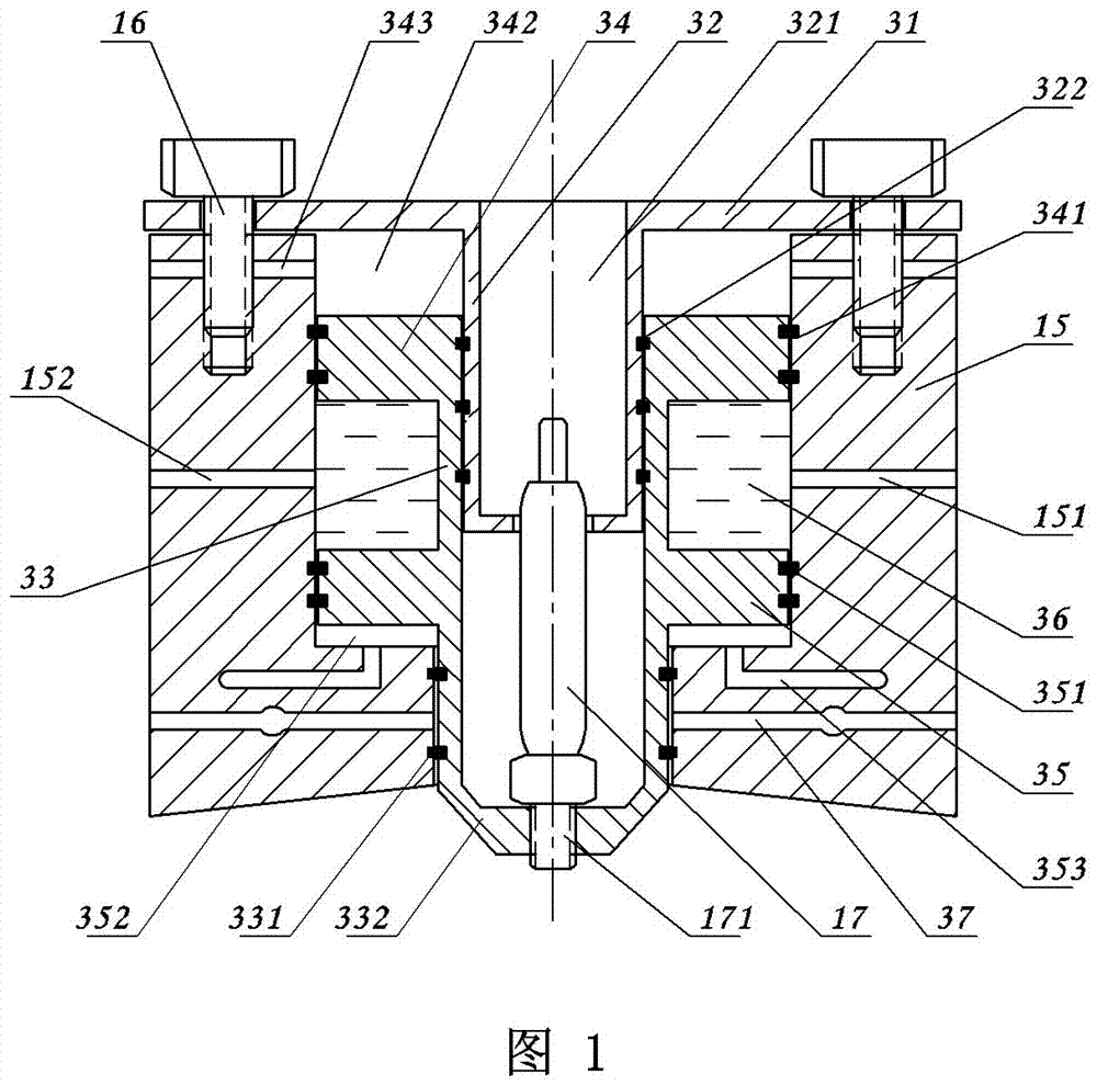
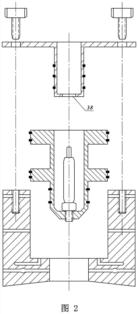
[0038] Embodiment 1: A kind of engine variable compression ratio mechanism, see figure 1 and figure 2 On the cylinder head, a circular hole communicating with the combustion chamber is opened at the installation position of the original spark plug at the top center of the combustion chamber as the auxiliary piston cylinder, and the auxiliary piston 33 is sealed and arranged in the auxiliary piston cylinder. After the circular hole is set and the auxiliary piston 33 is installed, the combustion chamber is still a complete closed space.

[0039] An auxiliary piston cover 31 is sealed and fixed on the top of the auxiliary piston cylinder to fix the auxiliary piston 33 . Wherein, a hollow structural cylinder is designed to extend downward at the center of the auxiliary piston cover 31, and a spark plug relief hole is arranged at the bottom thereof. The auxiliary piston 33 is also a hollow structure, and the hollow structure cylinder is sealed and sleeved on the inner surface of...

Embodiment 2

[0042] Embodiment 2: On the basis of Embodiment 1, the auxiliary piston 33 includes an upper annular piston and a lower annular piston and a cone-shaped hollow cylinder for installing a spark plug. The upper annular piston and the lower annular piston are respectively in sealing contact with the inner wall of the auxiliary piston cylinder. The conical hollow cylinder of the spark plug extends into the top of the combustion chamber, and its outer wall is in sealing contact with the inner surface of the channel communicating with the combustion chamber.

[0043] In this embodiment, the annular cavity formed between the upper annular piston and the lower annular piston is used as a cooling cavity, and the water inlet (or lubricating oil) port and the water (or lubricating oil) port communicating with the cooling cavity are respectively provided in the cylinder. Body cover.

[0044] The sliding mating surface that exists between the secondary piston 33 and the upper cover of the c...

Embodiment 3

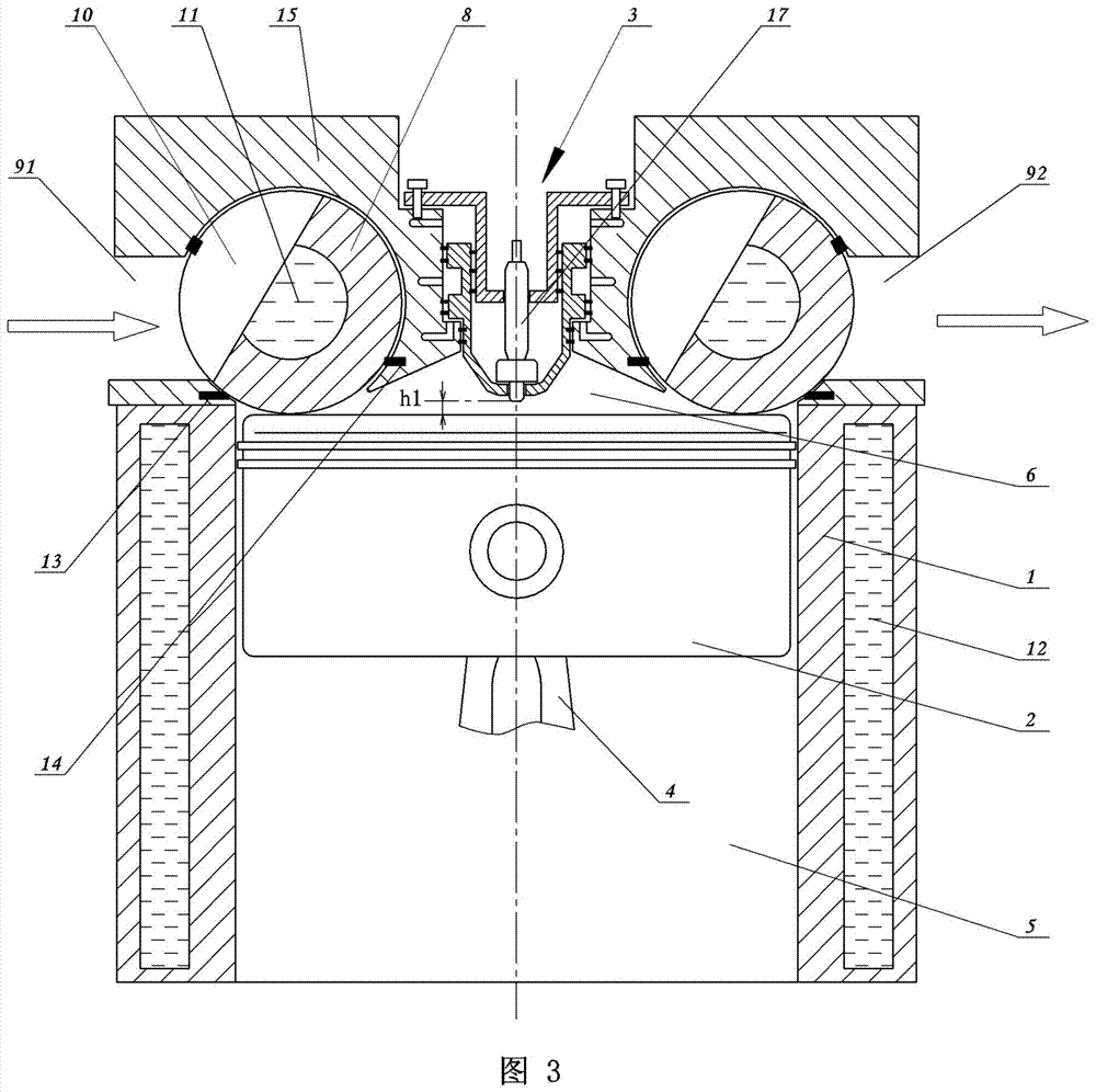
[0045] Embodiment 3: A gas distribution system containing a variable compression ratio mechanism, such as image 3 As shown, the intake valve and exhaust valve located at the top of the combustion chamber adopt the structure of intake valve shaft and exhaust valve shaft respectively. The combustion chamber is located at the top of the cylinder block 1, and the bottom of the cylinder block 1 is the piston 2, crankshaft and connecting rod 4 and other components.

[0046] For the specific structure of the valve shaft, see Figure 4 , on the intake valve shaft and the exhaust valve shaft, four (unlimited) protruding rotary valves whose outer diameter is larger than the outer diameter of the valve shaft are set. One side of the rotary valve is provided with a gap as an air flow channel 10, and the gap occupies a quarter of the circumference of the rotary valve.

[0047] The intake port 91 and the exhaust port 92 located at the top of the combustion chamber are respectively matche...


PUM


Abstract

The invention discloses a variable-compression-ratio mechanism of an engine and an air distribution system matched with variable-compression-ratio mechanism. An inner cavity is formed in the center position of the top of an air cylinder cover to serve as a hydraulic cylinder barrel. A piston cover is fixed to the top of the hydraulic cylinder barrel, and a hydraulic cylinder inner sleeve is arranged at the bottom of the center of the piston cover. An annular piston body is arranged in the hydraulic cylinder barrel in a sealed and sleeved manner. An upper oil cavity and a lower oil cavity are formed in the upper end and the lower end of the piston body correspondingly and communicate with an oil inlet pipe and an oil outlet pipe correspondingly. A spark plug installation head is arranged at the bottom of the annular piston body and is fixedly connected with a spark head. The compression ratio of the variable-compression-ratio mechanism can be adjusted in a stepless manner; the engine adopting the variable-compression-ratio mechanism is suitable for multi-fuel driving; emission can be better reduced; running stability is improved; torque is improved; implementation is simple, convenient and feasible; and the construction cost is low.

Description

technical field [0001] The invention belongs to the technical field of variable engine compression ratio, and specifically relates to a mechanism with simplified structure, valve cooling function, and variable engine compression ratio according to working conditions, and an air distribution system matched with the mechanism. Background technique [0002] The compression ratio of the current automobile engine is generally fixed and not variable. Variable compression ratio gasoline engines can accept a variety of fuels, but fuels with higher octane numbers are better for the engine, because the higher the octane number, the less likely it is to trigger knocking, so that the engine can use higher compression Ratio operation, so as to obtain higher thermal efficiency and lower fuel consumption. [0003] Because of the variable compression ratio technology, it is more efficient to use the supercharging system, and there is no need to worry about problems such as knocking caused ...

Claims


Application Information

Patent Timeline
IPC IPC(8): F01L7/02F01L7/18F01L13/08F02D15/04F02B23/10F01P3/14
CPCF01L7/02F01L7/18F01L13/08F01P3/14F02B23/10F02D15/04F02D2700/03Y02T10/12
Inventor 牛清锋
Owner 牛清锋
Learn More