Non-contact sample thickness measuring method and device based on Michelson interference principle

A sample thickness, non-contact technology, applied in the field of optical measurement, can solve the problems of high manufacturing cost of instruments, complicated and cumbersome design, etc., to reduce the measurement cost, avoid the illumination distribution, and simplify the measurement process.

Active Publication Date: 2017-06-20
SICHUAN UNIV
View PDF6 Cites 3 Cited by
  • Summary
  • Abstract
  • Description
  • Claims
  • Application Information

AI Technical Summary

Problems solved by technology

The key to the measurement accuracy of this method lies in the stability and accuracy of laser imaging; for this reason, the optical system design must achieve uniform illumination distribution on the image surface, less stray light, and small imaging geometric distortion. Not only is the design complicated and cumbersome, the instrument Manufacturing costs are also very high

Method used


Image

  • Non-contact sample thickness measuring method and device based on Michelson interference principle
  • Non-contact sample thickness measuring method and device based on Michelson interference principle
  • Non-contact sample thickness measuring method and device based on Michelson interference principle

Examples


Embodiment 1

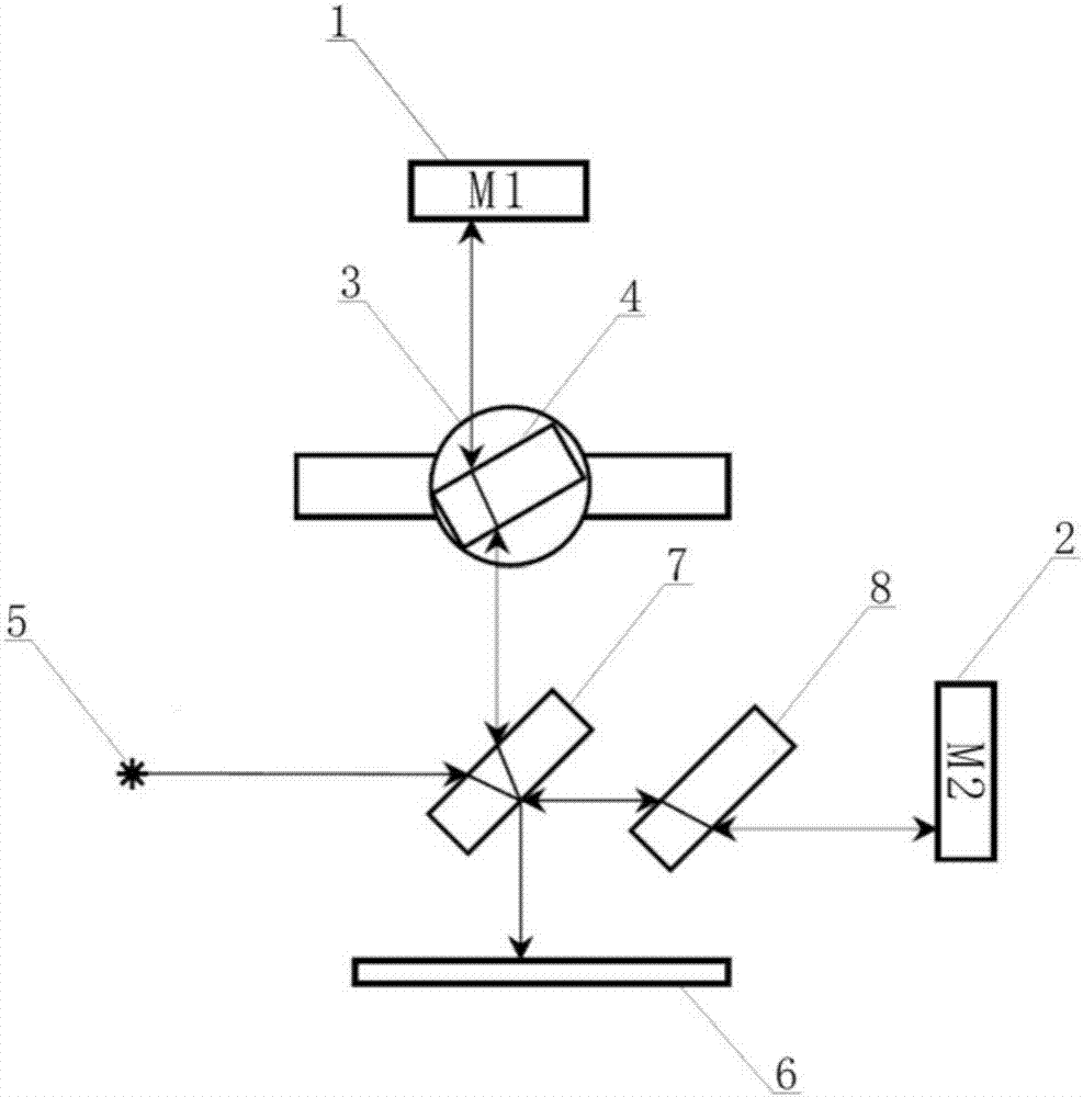
[0034] This embodiment provides a non-contact sample thickness measurement device based on Michelson interference principle, its structure is as follows figure 1 As shown, the measurement device includes a rotatable stage 3 and an optical path assembly mainly composed of an M1 reflector 1, an M2 reflector 2, a laser source 5, a receiving device 6, a beam splitter 7 and a compensation plate 8. The laser source 5, The beam splitter 7, the compensation plate 8 and the M2 reflector 2 are arranged in sequence along the same direction, the beam splitter 7 and the compensation plate 8 are parallel to each other and form an angle of 45° with the mirror surface of the M1 reflector; the rotatable stage 3 is located on the M1 reflector 1 and the splitter plate 7; the receiving device 6 is a receiving screen.

[0035] When the above-mentioned non-contact sample thickness measurement device based on the Michelson interference principle is used, the beam splitter 7 divides the laser light e...

Embodiment 2

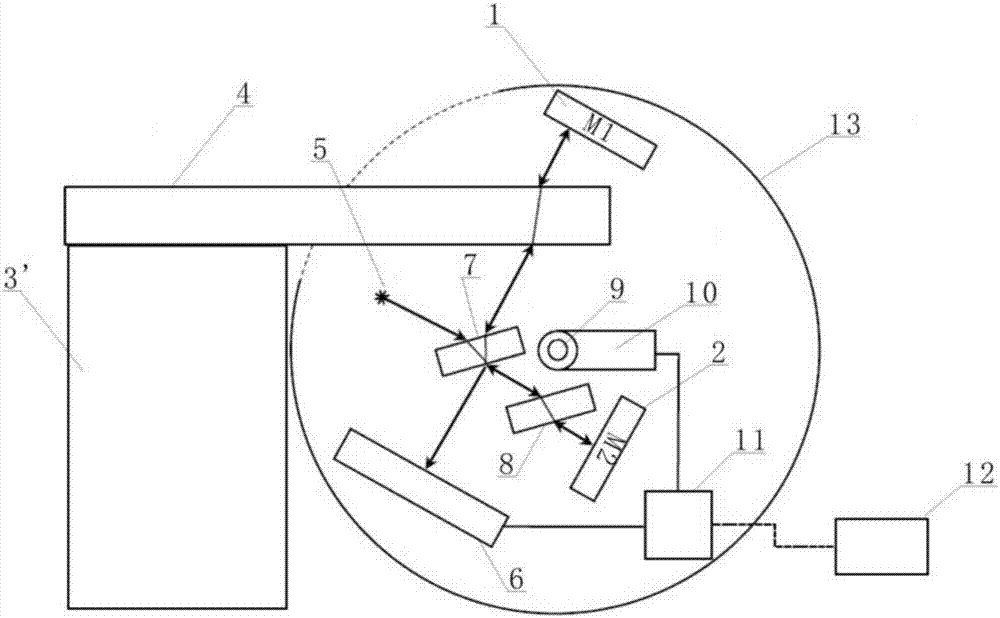
[0066] This embodiment provides a non-contact sample thickness measurement device based on Michelson interference principle, its structure is as follows image 3 As shown, the measuring device includes a fixed stage 3' for placing the sample 4 to be tested and an optical path assembly packaged in a casing 13; the optical path assembly is mainly composed of an M1 mirror 1, M2 mirror 2, laser source 5, receiving device 6, beam splitter 7, compensation board 8, micro-electromechanical gyroscope 10 and single-chip microcomputer 11; laser source 5, beam splitter 7, compensation board 8 and M2 mirror 2 are in the same direction Arranged in sequence, the beam splitter 7 and the compensation plate 8 are parallel to each other and form an angle of 45° with the mirror surface of the M1 mirror; the base is installed in the housing 13 through the central axis 9, and the micro-electromechanical gyroscope 10 is installed on the central axis 9 , to realize the linkage between base rotation a...

Embodiment 3

[0079] This embodiment provides a non-contact sample thickness measurement device based on Michelson interference principle, its structure is as follows Figure 4 As shown, the measuring device is basically the same as the device provided in Embodiment 2, the main difference is that the single-chip microcomputer 11 in this embodiment is arranged outside the casing 13 .


PUM


Abstract

The invention discloses a non-contact sample thickness measuring method and device based on the Michelson interference principle. By adjusting the angle between an M1 reflector and a sample plane, the optical path of a laser beam is changed, so that the interference fringe is displaced. Then, according to a formula provided by the invention, the thickness of a to-be-tested sample is obtained by calculation. As the measuring method only needs to control the physical quantity of the angle between the M1 reflector and the sample plane, the measuring error is extremely small, the measuring process is simplified and the accuracy of sample thickness measuring is improved. With regard to the measuring device used for achieving the measuring method, the measuring principle is simple and the high-precision expensive instrument is not required, so that the optical path assembly can be integrated into a one-piece device, and a miniature portable device is designed.

Description

technical field [0001] The invention belongs to the technical field of optical measurement, and in particular relates to a non-contact sample thickness measurement method and a measurement device based on the Michelson interference principle. Background technique [0002] For the measurement of sample thickness, contact measurement (for example, measurement with vernier caliper, screw micrometer and other instruments) or non-contact measurement (such as measurement method based on Michelson interferometry); however, in some special Under certain circumstances, high-precision non-contact measuring devices are irreplaceable. For example, in the manufacturing process of glass instruments, it is often necessary to measure properties such as thickness and refractive index of glass in a molten state; at this time, contact measurement The method not only has the potential to affect the shape and structure of the material, but also has limited precision. [0003] Therefore, many in...

Claims


Application Information

Patent Timeline
Patent Type & Authority Applications(China)
IPC IPC(8): G01B11/06
CPCG01B11/0675
Inventor 谭东杰关国业林方
Owner SICHUAN UNIV
Why Eureka
Try Eureka