A Standing Wave Calibration Method for Spatial Resolution of Near-field Probe Based on Transmission Line

A technology of spatial resolution, near-field probes, applied in the fields of magnetic field offset compensation, instruments, measuring devices, etc., can solve the problems of small changes, large calibration measurement errors, low excitation signal frequency, etc., to eliminate calibration errors, improve Calibration accuracy, excluding effects of randomness

Active Publication Date: 2019-05-17
BEIHANG UNIV
View PDF7 Cites 0 Cited by
  • Summary
  • Abstract
  • Description
  • Claims
  • Application Information

AI Technical Summary

Problems solved by technology

However, this method is relatively easy to introduce large calibration measurement errors. Taking the magnetic field probe as an example, the distribution of the field quantity on the moving path of the probe is not always orthogonal to the induction coil plane of the near-field probe, and the field distribution itself on the moving path of the probe It also has high complexity, and it is difficult to ensure consistency between the field quantity and the field-circuit coupling characteristics of the probe at each point during the probe movement process
The applicant also proposed "a traveling wave calibration method based on transmission line near-field probe spatial resolution", this method also has certain limitations, that is, when the working frequency of the calibrated near-field probe is low, The excitation signal frequency of the corresponding calibration scale also needs to be relatively low, which results in a small change in the field quantity relative to the spatial displacement within the limited length of the calibration scale, which is inconvenient for the calibration of the spatial resolution of the near-field probe

Method used


Image

  • A Standing Wave Calibration Method for Spatial Resolution of Near-field Probe Based on Transmission Line
  • A Standing Wave Calibration Method for Spatial Resolution of Near-field Probe Based on Transmission Line
  • A Standing Wave Calibration Method for Spatial Resolution of Near-field Probe Based on Transmission Line

Examples


Embodiment approach

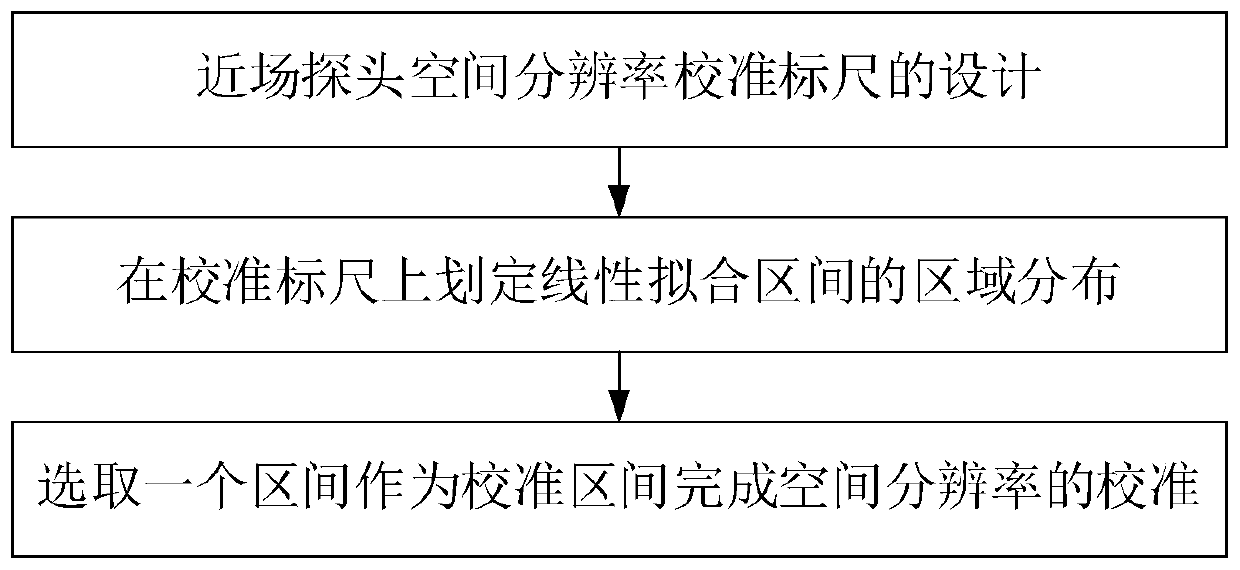
[0030] Such as figure 1 Shown, the specific implementation mode of the present invention is as follows:

[0031] Step 1: Design of the near-field probe spatial resolution calibration scale:

[0032] (1) The TEM wave field formed by the multi-conductor uniform transmission line in the TEM transmission mode:

[0033] When the electromagnetic wave propagates under the boundary conditions composed of multi-conductor planar transmission lines, it is equivalent to propagating in a weakly conductive medium. With the increase of the transmission distance, the field strength amplitude in the electromagnetic wave will attenuate, but for the frequency For low signal, this attenuation is negligible within a limited transmission distance. Based on the propagation theory of electromagnetic waves in weakly conductive media, combined with the simulation results of three-dimensional full-wave electromagnetic fields and existing empirical formulas, the corresponding equations for describing t...


PUM


Abstract

The invention derives a more effective way of description from the traditional definition on the probe spatial resolution, and put forward a spatial resolution calibration method based on the controllable probe with axial-distribution EMF above the planar transmission lines, including to give derivative definition on the probe spatial resolution through normalization, to set up controllable probe calibration platform with axial distribution of EMF above the planar transmission line; suitable for spatial resolution calibration with travelling wave in case of high frequency and standing wave in case of low frequency, which can effectively control and reduce the errors generated by the probe size as well as sensitivity, high frequency and low frequency of signal detection equipment.

Description

technical field [0001] The invention relates to a standing wave calibration method for the spatial resolution of a near-field probe based on a transmission line, belonging to the field of antenna measurement. Background technique [0002] In the process of board-level electromagnetic interference (EMI: Electromagnetic Interference) problem analysis and rectification, near-field probes are often used to locate radiation sources on printed circuit boards (PCB: Printed Circuit Board). As an important technical parameter of the near-field probe, the spatial resolution has a very important impact on the accuracy of positioning. [0003] Currently, the calibration method for the spatial resolution of the available near-field probe is to excite a microstrip line, and then move the near-field The probe is then measured by a receiver or a spectrum analyzer in the near-field EMI test system to obtain a field distribution curve, and the spatial resolution of the near-field probe is gi...

Claims


Application Information

Patent Timeline
Patent Type & Authority Patents(China)
IPC IPC(8): G01R35/00
CPCG01R35/005G01R29/0828G01R29/0878G01R33/0017
Inventor 戴飞高占威符新凯周芳宇
Owner BEIHANG UNIV
Why Eureka
Try Eureka