Integrated coking furnace desulfurization and denitrification system

A technology for desulfurization, denitrification, and coking furnaces, which is applied in gas treatment, chemical instruments and methods, and dispersed particle separation. Fast, high degree of automation, small equipment changes

Inactive Publication Date: 2017-06-23
黄胜建
6 Cites 0 Cited by

AI-Extracted Technical Summary

Problems solved by technology

Its shortcoming is: (1) denitrification efficiency is low, and denitrification efficiency is 30%-50%, can not meet existing environmental protection requirement; Efficiency has an impact...

Abstract

The invention relates to an integrated coking furnace desulfurization and denitrification system, which comprises an ozone generator (1), an ozone metering system (2), an ozone filling system (3), a hydrogen peroxide storage tank (4), a hydrogen peroxide metering system (5) and a hydrogen peroxide filling system, wherein a gas outlet of the ozone generator (1) is connected with the ozone metering system (2) through a pipeline, the ozone metering system (2) is connected into a flue before a desulfurization tower (7) through the ozone filling system (3), the hydrogen peroxide filling system is arranged between a desulfurization spraying layer and a defogging plate of the desulfurization tower (7), the hydrogen peroxide filling system is connected with the hydrogen peroxide metering system (5) through a pipeline, and the hydrogen peroxide metering system (5) is connected with the hydrogen peroxide storage tank (4) through a hydrogen peroxide pump (6). Compared with the prior art, the system has the advantages of high denitrification efficiency, smaller equipment size, slight modification on original equipment, no ammonia water, no ammonia escape, adaptability to violent changes of flue gas flow and high automation degree.

Application Domain

Technology Topic

Image

  • Integrated coking furnace desulfurization and denitrification system

Examples

  • Experimental program(1)

Example Embodiment

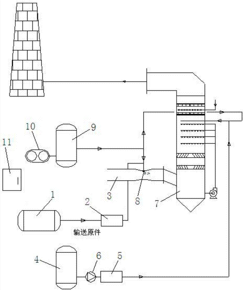
[0023] Below in conjunction with accompanying drawing, the present invention will be further described as follows:
[0024] as attached figure 1 As shown, the present invention is used for desulfurization and denitrification treatment of flue gas produced by coke ovens. The system includes: ozone generator 1, ozone metering system 2, ozone filling system 3, hydrogen peroxide storage tank 4, hydrogen peroxide metering system 5 and hydrogen peroxide adding Injection system, the gas outlet of the ozone generator 1 is connected to the ozone metering system 2 through the pipeline, and the ozone metering system 2 is connected to the flue in front of the desulfurization tower 7 through the ozone filling system 3, between the desulfurization spray layer of the desulfurization tower 7 and the defogging plate A hydrogen peroxide filling system is provided in the room, and the hydrogen peroxide filling system is connected to the hydrogen peroxide metering system 5 through pipelines, and the hydrogen peroxide metering system 5 is connected to the hydrogen peroxide storage tank 4 through the hydrogen peroxide pump 6. As a preferred technical solution of the present invention, a scrubber can also be arranged above the desulfurization and denitrification system, and the scrubber is connected with a chimney.
[0025] In the present invention, the inlet flue of the desulfurization tower 7 is provided with a Venturi injection nozzle 8, and the Venturi injection nozzle 8 is connected to the compressed air storage tank 9 through a pipeline, and the air inlet of the compressed air storage tank 9 is connected to the air compressor 10. Connected, the air outlet of the compressed air storage tank 9 is also connected to the hydrogen peroxide filling system through a pipeline. The hydrogen peroxide filling system includes a hydrogen peroxide filling nozzle, and the hydrogen peroxide filling nozzle is arranged at a position between the desulfurization spray layer and the defogging plate in the desulfurization tower 7 . It also includes an electric control system 11, an ozone generator 1, an ozone metering system 2, a hydrogen peroxide metering system 5, a hydrogen peroxide pump 6, and an air compressor 10 are respectively connected to the electric control system 11 through lines.
[0026] In the present invention, the ozone generator generates ozone, the amount to be filled is measured by the ozone metering system, and then the ozone is transported to the flue in front of the desulfurization tower by the ozone filling system. The hydrogen peroxide in the hydrogen peroxide storage tank is metered and output by the hydrogen peroxide metering system, and then sent to the hydrogen peroxide filling system between the spray layer of the desulfurization tower and the demister plate through the hydrogen peroxide pump. Based on the original hydrogen peroxide oxidation method, the device combines ozone with stronger oxidizing property, reduces the consumption of hydrogen peroxide, improves the denitrification efficiency, and solves the denitrification problem of low-temperature flue gas.
[0027] According to the amount of nitrogen oxides in the coke oven flue gas, the ozone metering system measures a certain amount of ozone and transports it to the Venturi injection nozzle on the inlet flue of the desulfurization tower. The compressed air injects the ozone, fully mixes with the flue gas, and oxidizes with nitrogen. reaction. Set H between the desulfurization spray layer of the desulfurization tower and the demister 2 0 2 Filling the nozzle, the hydrogen peroxide is transported from the delivery device to the metering device to control the output amount, and injected into the flue gas through the compressed air injection nozzle. Due to the large amount of SO in flue gas 2 The gas has been removed, H 2 o 2 Raising at this position will not be associated with SO 2 reaction, reducing the H 2 o 2 dosage.
[0028] In practical application, the specific reaction process is:
[0029] (1) Ozone denitrification reaction:
[0030] NO+O3→NO2+O2
[0031] NO2+O3→NO3+O2
[0032] NO3+NO2→N2O5
[0033] NO+O+M→NO2+M
[0034] NO2+O→NO3
[0035] (2) Hydrogen peroxide denitrification reaction:
[0036] 2NO 2 +H 2 O(liquid phase)→HNO 3 +HNO 2
[0037] HNO 2 +NO 2 →HNO 3 +NO
[0038] 2NO 2 +H 2 o 2 (liquid phase)→2HNO 3
[0039] HNO 2 +H 2 o 2 (liquid phase)→HNO 3 +H 2 o
[0040] NO+NO 2 +H 2 o 2 (liquid phase)→2HNO 3
[0041] SO 2 +H 2 o 2 (liquid phase)→H 2 SO 4
[0042] Since coke oven denitrification has fluctuating flue gas flow, high concentration, and low flue gas temperature, generally only 200°C-300°C, the optimum reaction temperature of SCR catalysts is generally 350°C-420°C. Therefore, the use of conventional SCR catalysts is difficult to operate effectively, and the low-temperature catalysts (meaning meeting the temperature window below 320°C) that have been researched so far are immature, and their operating life and anti-pollution capabilities are not ideal. Especially for coking furnace flue gas, due to insufficient sealing during work. A small amount of coke oven gas is often mixed into the flue gas, and traces of reducing sulfides (such as chlorine sulfide, carbon disulfide and organic sulfur, etc.) have a strong poisonous effect on the SCR micro-chemical agent, which can easily lead to catalyst deactivation.
[0043] In view of the above shortcomings of the current technology, a new technology and process for the integration of desulfurization and denitrification of coking flue gas is proposed, which is the oxidation and absorption method of nitrogen oxides. Its essence is to use some oxidizing substances such as (ozone, hydrogen peroxide, etc.) to oxidize nitrogen oxides in the form of NO (insoluble in water) in the flue gas to NO 2.and NO 2 Then the soluble alkaline solution can be removed by the alkaline desulfurization solution together with sulfur dioxide.
[0044] Ozone and nitrogen oxides in the flue gas are both in the gaseous state, and react quickly with NOx in the same gas phase. 2 The reaction is selective, preferentially reacting with NOx. The oxidation method does not use a catalyst, which avoids the problems of catalyst poisoning and failure and low-temperature catalyst immaturity, and does not need to modify the coke oven body at the same time. All the process requirements for the ozone oxidation method, hydrogen peroxide oxidation method and ozone hydrogen peroxide combined oxidation method involved in the desulfurization and denitrification project of the coking furnace belong to the scope of protection of the patent right of the present invention.
[0045] The present invention is not limited by the above-mentioned embodiments, and any other changes, modifications, substitutions, combinations, and simplifications that do not deviate from the spirit and principles of the present invention should be equivalent replacement methods and are included in the present invention. within the scope of protection.

PUM

no PUM

Description & Claims & Application Information

We can also present the details of the Description, Claims and Application information to help users get a comprehensive understanding of the technical details of the patent, such as background art, summary of invention, brief description of drawings, description of embodiments, and other original content. On the other hand, users can also determine the specific scope of protection of the technology through the list of claims; as well as understand the changes in the life cycle of the technology with the presentation of the patent timeline. Login to view more.

Similar technology patents

Classification and recommendation of technical efficacy words

  • Improve denitrification efficiency
  • Equipment is small

Ammonia flue gas desulfuration and denitration combined process and device

InactiveCN103041678APromote denitrificationImprove denitrification efficiencyUsing liquid separation agentPerfluorocarbons/hydrofluorocarbons captureFomesChemistry
Owner:ZHEJIANG TIANLAN ENVIRONMENTAL PROTECTION TECH

Test system used for satellite power supply and distribution system

InactiveCN104503421AEquipment is smallReduce refactoring timeElectric testing/monitoringSatelliteElectric power distribution
Owner:AEROSPACE DONGFANGHONG SATELLITE
Why Eureka
Try Eureka