A photovoltaic module lamination device

A technology for photovoltaic modules and lamination devices, which can be used in lamination devices, lamination, photovoltaic power generation, etc., can solve the problems of air bubbles, photovoltaic sheet damage, waste of resources, etc., and achieve energy saving, improved automation, and uniform heating temperature. Effect

Active Publication Date: 2018-12-25
重庆昊格新能源集团有限公司
View PDF9 Cites 0 Cited by
  • Summary
  • Abstract
  • Description
  • Claims
  • Application Information

AI Technical Summary

Problems solved by technology

[0003] At present, the lamination process in the production process of photovoltaic modules is mostly carried out by using a laminator. In the process of lamination, EVA is mostly used now, but the process of using EVA has strict requirements on temperature, and the fluctuating temperature is easy to cause Bubbles are generated during the lamination process, which will cause damage to the photovoltaic sheet in severe cases. At the same time, the process of heating up to melt the EVA and cooling and solidification is required during the lamination process. In the current use process, the hot air at the vacuum pump is not reused, which will cause serious waste of resources

Method used


Image

  • A photovoltaic module lamination device
  • A photovoltaic module lamination device
  • A photovoltaic module lamination device

Examples


Embodiment Construction

[0019] The following will clearly and completely describe the technical solutions in the embodiments of the present invention with reference to the accompanying drawings in the embodiments of the present invention. Obviously, the described embodiments are only some, not all, embodiments of the present invention. Based on the embodiments of the present invention, all other embodiments obtained by persons of ordinary skill in the art without making creative efforts belong to the protection scope of the present invention.

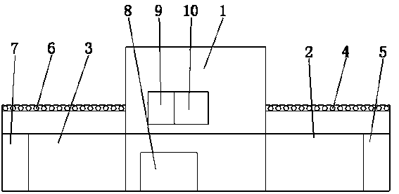
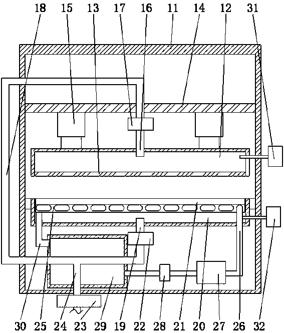
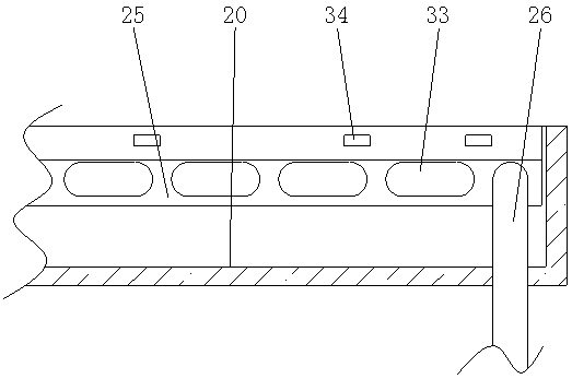
[0020] see Figure 1 to Figure 3 , in an embodiment of the present invention, a photovoltaic module lamination device includes a main machine 1, the right side of the main machine 1 is a feeding device 2, the upper side of the feeding device 2 is provided with a feeding conveyor belt 4, and the lower side of the feeding conveyor belt 4 A feeding power box 5 is provided, a discharge device 3 is provided on the left side of the main machine 1, a discharge convey...


PUM


Abstract

The invention discloses a photovoltaic module laminater which comprises a host machine, wherein the front side of the host machine is provided with a control center; a display panel is arranged above the control center; the right side of the display panel is provided with control buttons; the host machine comprises a host machine housing; the upper part in the host machine housing is provided with a support bar; an electrohydraulic cylinder is arranged under the support bar; the lower part of the electrohydraulic cylinder is connected with a lamination upper chamber through a piston rod; the lower side of the lamination upper chamber is provided with a silica gel plate; the upper side of the lamination upper chamber is connected with an upper chamber pipeline; the lower part of the host machine housing is connected with a lamination lower chamber; the lower side of the lamination lower chamber is connected with a lower chamber pipeline; a worktable is arranged above the lamination lower chamber; and the lower side of the worktable is provided with a heating layer. The structure is novel: by arranging the feeder and discharger, the automation degree of the lamination process is enhanced, so that the EVA (ethylene-vinyl acetate) heating temperature is uniform; the arranged temperature sensor can perform accurate control on the temperature of the photovoltaic module; and besides, the high-temperature gas at the vacuum pump is reutilized, thereby saving the energies and lowering the production cost.

Description

technical field [0001] The invention relates to the field of photovoltaic module production equipment, in particular to a photovoltaic module lamination device. Background technique [0002] A photovoltaic panel module is a power generation device that generates direct current electricity when exposed to sunlight. It consists of thin, solid photovoltaic cells almost entirely made of semiconductor materials such as silicon. Since there are no moving parts, it can be operated for a long time without any wear and tear. Simple photovoltaic cells power watches and calculators, and more complex photovoltaic systems light homes and power the grid. Photovoltaic panel assemblies can be made in different shapes, and the modules can be connected to generate more electricity. [0003] At present, the lamination process in the production process of photovoltaic modules is mostly carried out by using a laminator. In the process of lamination, EVA is mostly used now, but the process of u...

Claims


Application Information

Patent Timeline
Patent Type & Authority Patents(China)
IPC IPC(8): B32B37/10B32B38/18H01L31/048H01L31/18H01L31/049
CPCB32B37/1018B32B38/18B32B2457/12H01L31/048H01L31/049Y02E10/50Y02P70/50
Inventor 陆永振
Owner 重庆昊格新能源集团有限公司
Why Eureka
Try Eureka