A manufacturing method of a high-precision carbon fiber ring-focus antenna sub-reflector

A technology of sub-reflector and ring-focus antenna, which is applied in the field of communication, can solve the problems of low honeycomb density of aramid paper, difficulty in molding, complicated molding steps, etc., and achieve the effects of strong accuracy, simplified molding steps, and reduced production costs

Active Publication Date: 2019-06-28
NO 54 INST OF CHINA ELECTRONICS SCI & TECH GRP +1
View PDF4 Cites 0 Cited by
  • Summary
  • Abstract
  • Description
  • Claims
  • Application Information

AI Technical Summary

Problems solved by technology

Aluminum honeycomb is made of aluminum foil, which has good rigidity and high shear resistance. However, the thermal expansion coefficient of aluminum honeycomb and carbon fiber composite materials is two orders of magnitude different, and it is easy to generate large stress when forming. Aramid paper honeycomb has a small density and high compression. Strength and shear strength, easy to coordinate with carbon fiber assembly, but the curvature of the ring focus secondary reflector described in this article changes greatly, it is not easy to form, and if aramid paper honeycomb is used, it needs to be cured in advance, the forming step complex
[0005] The key point and difficulty of forming the sub-reflector of carbon fiber ring focus antenna is the molding of the convex point. First, the mold for forming the convex point is not easy to process. Second, when forming the convex point, if the pressure transmission is not in place, it is easy to form a convex point Some parts are not attached to the mold. Third, after molding, if the force is improper or the operation is incorrect, the convex tip will be easily damaged during demoulding.

Method used


Image

  • A manufacturing method of a high-precision carbon fiber ring-focus antenna sub-reflector
  • A manufacturing method of a high-precision carbon fiber ring-focus antenna sub-reflector

Examples


Embodiment Construction

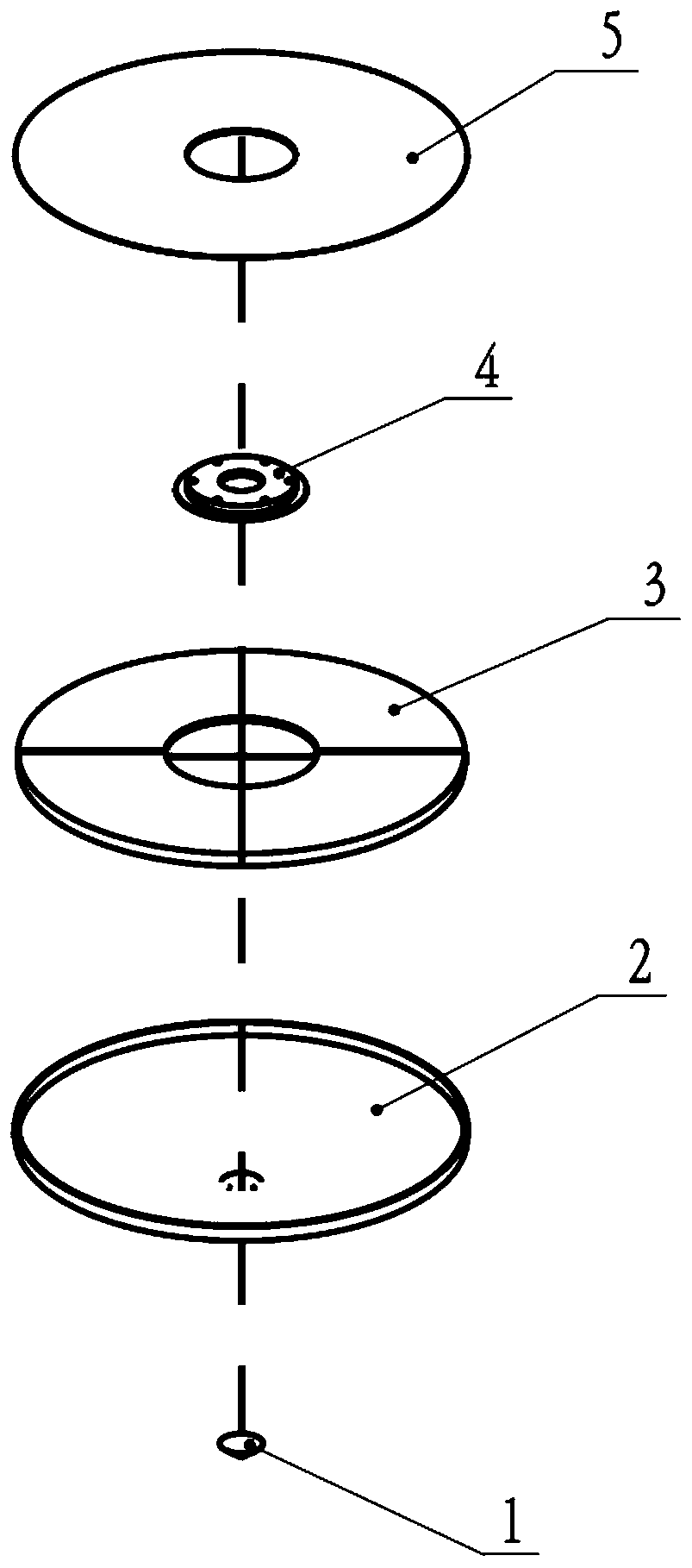
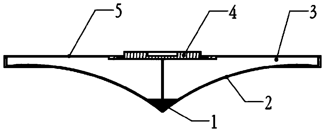
[0036] to combine figure 1 and figure 2 , the present invention will be further described below.

[0037] Provides a high-precision carbon fiber ring-focus antenna sub-reflector, including a convex point 1, an outer skin 2, a sandwich core 3, a metal embedded part 4, and an upper skin 5. The convex point 1 is composed of a metal reflective layer and Multiple layers of circular inner carbon fiber prepregs of decreasing diameter are composited together to form the cone. The outer skin 2 includes a composite metal reflective layer and an outer skin carbon fiber prepreg cladding layer, and a sandwich material 3 is arranged above the convex point in the outer skin, and the sandwich material is foam. The upper skin 5 is covered above the sandwich material 3, the upper skin is a carbon fiber prepreg laying layer, the bottom surface of the sandwich is flat, and the top surface of the convex point can just be butted on the bottom surface of the sandwich to form The outer wall is a ...


PUM


Abstract

The invention discloses a method for manufacturing a high-precision carbon fiber ring-focus antenna sub-reflector, which relates to the field of radar antenna manufacturing engineering. It is integrated with the preparation of the sandwich material in the middle of the upper skin, especially in the process of preparing the convex point, a new coating spinning process is adopted, which greatly reduces the production time and improves the product quality. The invention adopts integral molding technology, cleverly uses the foam sandwich structure, simplifies the technological process, and manufactures a high-precision carbon fiber ring-focus antenna sub-reflector, whose precision meets the design requirements, and has good electrical performance test results. It is especially suitable for mass production of secondary reflectors of ring-focus antennas on mobile carriers such as vehicles and ships.

Description

technical field [0001] The invention relates to a method for manufacturing a secondary reflection surface of a high-precision carbon fiber ring-focus antenna in the field of communication. It is especially suitable for mass production of secondary reflectors of ring-focus antennas on mobile carriers such as vehicles and ships. Background technique [0002] The accuracy of the sub-reflector of the antenna has a great influence on the gain and efficiency of the antenna. As the surface accuracy of the sub-reflector decreases, the gain and efficiency of the antenna will also decrease. Therefore, improving the stiffness and precision of the sub-reflector is very important in the design of the antenna sub-reflector. As the weight of the sub-reflector increases, the self-weight deformation will also increase. How to improve the accuracy and stiffness and reduce the self-weight deformation is the problem we need to solve. [0003] The production process of the traditional ring-foc...

Claims


Application Information

Patent Timeline
Patent Type & Authority Patents(China)
IPC IPC(8): H01Q15/14H01Q15/16
CPCH01Q15/141H01Q15/16
Inventor 卜敬王海东宁晓磊滑聪王庆东米宏伟石晓改
Owner NO 54 INST OF CHINA ELECTRONICS SCI & TECH GRP
Why Eureka
Try Eureka