Eureka AIR delivers breakthrough ideas for toughest innovation challenges, trusted by R&D personnel around the world.

Large-pitch special-shaped spiral drill rod

A technology of auger rod and large pitch, which is used in drill rods, drill pipes, and earth-moving drilling and mining, etc., can solve the problems of sticking, holding the drill, the friction between the helical blade and the body of the drill pipe, etc., so as to improve the drilling depth. , Improve the slag discharge efficiency and enhance the effect of the slag discharge function

Inactive Publication Date: 2017-06-27
CHONGQING UNIV OF ARTS & SCI
View PDF0 Cites 10 Cited by
  • Summary
  • Abstract
  • Description
  • Claims
  • Application Information

AI Technical Summary

Problems solved by technology

[0002] The problem of drilling in broken and soft coal seams has always been a difficult problem in the drilling construction of coal seam gas drainage in mines at home and abroad, especially in soft and outburst mines with high ground stress and high gas. The rod can no longer meet the construction requirements of the gas drainage hole
Among them, the blades of ordinary auger pipes are relatively high, and there are more coal chips in the broken soft coal seam, which causes the friction force of the coal chips on the helical blades and the drill pipe body to be relatively large, so it is easy to cause slag discharge and blockage during the drilling process In some cases, when the friction torque of coal cuttings on the drill pipe exceeds the rated torque of the drilling rig, accidents such as drill sticking, drilling or even drill drop will occur; the slag discharge of the triangular drill pipe is better than that of the ordinary helical drill pipe, because its The special cross-sectional shape of the drill pipe provides more discharge space for the coal dust, and because the outer surface of the drill pipe is prism-shaped, the prism can prevent the coal dust from settling, but there is no power to transport the coal dust out of the hole. The compressed air is blown out of the hole, so the drilling depth is greatly restricted, and there is a great potential safety hazard

Method used


Image

  • Large-pitch special-shaped spiral drill rod
  • Large-pitch special-shaped spiral drill rod
  • Large-pitch special-shaped spiral drill rod

Examples


Embodiment 1

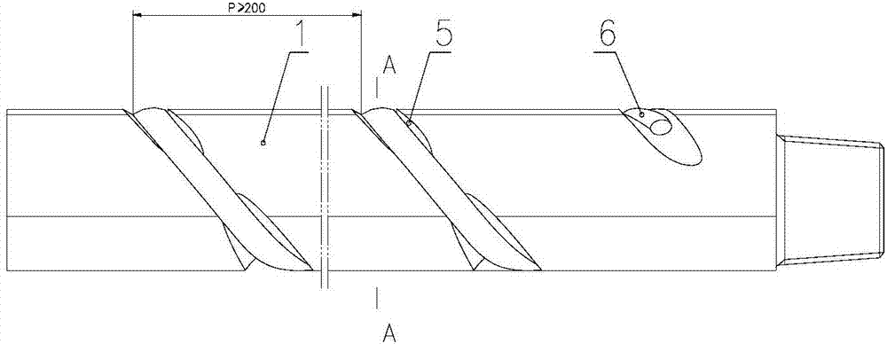
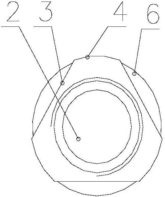
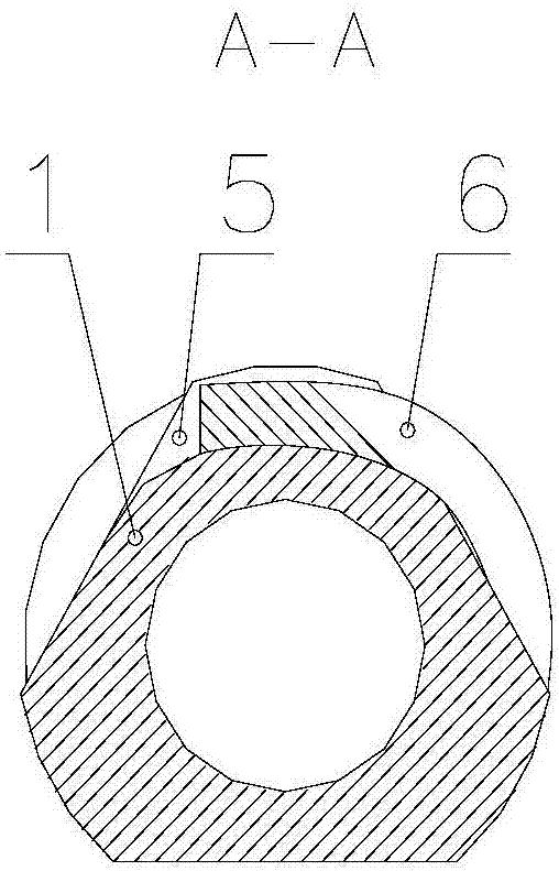
[0030] Embodiment one: if Figure 1-3 As shown, a large-pitch special-shaped helical drill pipe includes a drill pipe body 1 with a medium delivery channel 2 inside, and the two ends of the drill pipe body 1 are respectively provided with external threads and internal threads for mutual connection. The outline is composed of three straight line segments 3 of equal length and three arc line segments 4 of equal length arranged at intervals and connected from head to tail. The outer wall of the drill pipe body 1 is provided with a spiral groove 5, and the pitch of the spiral groove 5 is greater than or equal to 200 mm. A helical blade 6 is provided, and the helical groove 5 is intermittently arranged in the middle part of the straight section of the outer contour of the drill pipe body to form a discontinuous helical groove. The cross section of the helical groove 5 is arc-shaped, and the helical blade 6 is a continuous helical blade , the cross section of the spiral blade 6 is c...

Embodiment 2

[0031] Embodiment two: if Figure 4-6 As shown, the difference from Embodiment 1 is that the drill pipe body 1 includes a rod body 11, a male joint 12 and a female joint 13 fixedly connected by friction welding, the external thread is arranged on the male joint 12, and the internal thread is arranged on the female joint 13 superior. In the embodiment, the external thread on the male joint and the internal thread on the female joint are processed first, and the external thread and the internal thread are treated with nitriding, high-frequency quenching, phosphating or nickel-phosphorus plating; then the male joint and the female joint are It is fixedly connected with the drill pipe body by friction welding; then the spiral groove and three cutting surfaces are processed, and finally the spiral blade is fixed on the bottom of the spiral groove by welding. Nitriding, high-frequency quenching, phosphating or nickel-plated phosphorus treatments are used for the external thread and...

Embodiment 3

[0032] Embodiment three: as Figure 7 As shown, the difference from Embodiment 1 lies in the cross-sectional profile of the drill pipe body 1. The cross-sectional profile of this embodiment is composed of four equal-length straight line segments 3 and four equal-length arc line segments 4 end-to-end connected at intervals.


PUM


Abstract

The invention relates to a large-pitch special-shaped helical drill rod, which includes a drill rod body provided with a medium conveying channel inside. The two ends of the drill rod body are respectively provided with external threads and internal threads. Composed of arc segments, the straight segment and the arc segment are arranged at intervals, the head and tail are connected with each other and the number is equal, the arc segment is not less than two, the outer wall of the drill rod is provided with a spiral groove, the A helical blade is arranged in the helical groove. The purpose of the present invention is to increase the slag discharge capacity by setting the spiral blade in the spiral groove on the outer wall of the drill pipe, and prevent the coal dust from being blocked in the gap between the drill pipe and the coal wall to cause gas accumulation, difficult drilling, and even drill sticking , Drill drop and other accidents in the hole, improve the hole formation rate and drilling efficiency; by nitriding, high-frequency quenching, phosphating or nickel-phosphorus treatment on the internal and external threads of the drill pipe body, avoid The internal and external threads are bonded together, which makes the removal of the drill pipe easier.

Description

technical field [0001] The invention belongs to the technical field of underground gas drainage drilling in coal mines, and relates to a special-shaped helical drill rod with a large pitch. Background technique [0002] The problem of drilling in broken and soft coal seams has always been a difficult problem in the drilling construction of coal seam gas drainage in mines at home and abroad, especially in soft and outburst mines with high ground stress and high gas. The rod has been unable to meet the construction requirements of the gas drainage hole. At present, in the mining and utilization process of soft and outburst coal seams, drilling rigs and negative pressure suction are still used for gas control, and ordinary auger drill pipes or triangular drill pipes are mostly used as drill pipes. Among them, the blades of ordinary auger pipes are relatively high, and there are more coal chips in the broken soft coal seam, which causes the friction force of the coal chips on t...

Claims


Application Information

Patent Timeline
Patent Type & Authority Applications(China)
IPC IPC(8): E21B17/22E21B17/042
CPCE21B17/22E21B17/042
Inventor 唐大勇赵华君胡旭
Owner CHONGQING UNIV OF ARTS & SCI
Why Eureka
Eureka Blog
Learn More