Thin film inductor and power supply conversion circuit

A thin-film and inductive technology, applied in circuits, output power conversion devices, transformer/inductor components, etc., can solve the problems of current surge, burnt devices, and inductance reduction in circuit conversion circuits, reducing circulation and reducing magnetic flux. resistance, reducing the effect of easy saturation

Active Publication Date: 2017-06-30
HUAWEI MACHINERY
View PDF5 Cites 9 Cited by
  • Summary
  • Abstract
  • Description
  • Claims
  • Application Information

AI Technical Summary

Problems solved by technology

However, since the magnetic thin film material has such figure 1 The direction in which it is difficult for magnetic flux to flow (referred to as the direction of hard magnetization for ease of understanding and description) and the direction of easy flow of magnetic flux (referred to as the direction of easy magnetization for ease of understanding and description), wherein, along the direction of easy magnetization, The large magnetic permeability makes the magnetic flux in the thin film magnetic core very easy to saturate in the direction of easy magnetization, which leads to the magnetic permeability close to zero, which makes the inductance drop sharply, the current in the circuit conversion circuit increases sharply, and even burns the device in serious cases

Method used


Image

  • Thin film inductor and power supply conversion circuit
  • Thin film inductor and power supply conversion circuit
  • Thin film inductor and power supply conversion circuit

Examples


preparation example Construction

[0139] Figure 9 is a schematic flowchart of a method 400 for manufacturing a thin film inductor according to an embodiment of the present invention. Such as Figure 9 As shown, the preparation method 400 includes:

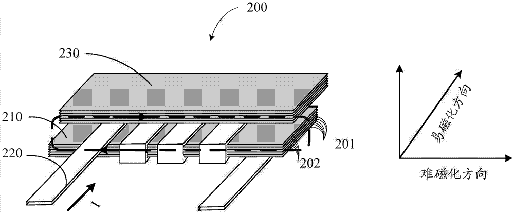
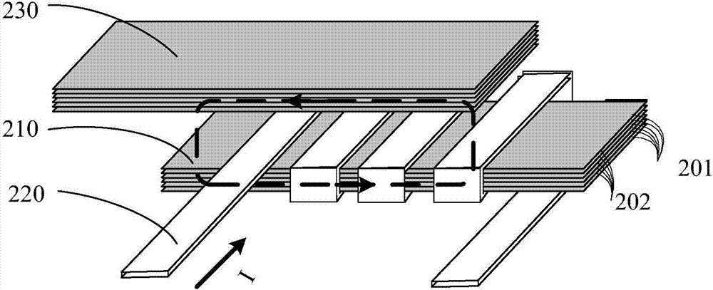
[0140] S410, configuring the first thin film magnetic core 210;

[0141] S420, wind at least one winding on the first thin film magnetic core 210 along the hard magnetization direction of the first thin film magnetic core 210, wherein the projection of the at least one winding 220 on the first plane surrounds the first thin film magnetic core The projection of the core on the first plane, the first plane is perpendicular to the hard magnetization direction of the first thin film magnetic core 210;

[0142] S430, configuring at least one second thin film magnetic core 230, the at least one second thin film magnetic core 230 is not wound with a winding, and each second thin film magnetic core 230 in the at least one second thin film magnetic core 230 is connected...


PUM


Abstract

The embodiment of the invention provides a thin film inductor. The thin film inductor comprises a first thin film magnetic core and at least one second thin film magnetic core (230); at least one winding (220) is wound on the first thin film magnetic core (210) in the hard magnetization direction of the first thin film magnetic core (210); no winding is wound on the second thin film magnetic cores (230), each second thin film magnetic core (230) is not in the same plane with the first thin film magnetic core (210), the hard magnetization direction of each second thin film magnetic core (230) is same as that of the first thin film magnetic core (210), and projections, on a second plane, of the second thin film magnetic cores (230) and the first thin film magnetic core (210) are at least partially overlapped. The risk that magnetic flow is easily saturated in the easy magnetization direction can be reduced, and better inductance can be produced.

Description

technical field [0001] Embodiments of the present invention relate to the field of circuits, and more specifically, relate to a thin film inductor and a power conversion circuit. Background technique [0002] The power conversion system of the chip power supply is developing in the direction of miniaturization, and the main device in the power conversion system, the inductance, has a large volume and is difficult to integrate into the processor. At present, a high-frequency silicon-based copper-magnetic material-copper (CopperMagnetic Copper, CMC) thin film inductor is known. The thin film magnetic core in this thin film inductor is made of multi-layer magnetic thin films, and the shape can be closed. Or a rod-shaped open type. [0003] In the existing technology, such as figure 1 As shown, in order to obtain a larger inductance, a closed-shaped thin-film magnetic core structure is adopted, so that the magnetic flux generated by the winding is at figure 1 Continuous flow ...

Claims


Application Information

Patent Timeline
Patent Type & Authority Applications(China)
IPC IPC(8): H01F27/245H01F27/30H01F27/34H01F41/00H02M3/158
CPCH01F27/245H01F27/306H01F27/34H01F41/00H02M3/1584
Inventor 杨仕军杨和钱朱勇发陈为
Owner HUAWEI MACHINERY
Why Eureka
Try Eureka