Surface emitting laser and preparation method thereof

A surface emitting laser, confinement layer technology, applied in the field of lasers, can solve the problems of device failure, poor temperature resistance, large volume change, etc., to achieve the effect of improving stability, high thermal conductivity and electrical conductivity, and reducing process difficulty

Inactive Publication Date: 2017-07-07
SUZHOU INST OF NANO TECH & NANO BIONICS CHINESE ACEDEMY OF SCI
View PDF15 Cites 9 Cited by
  • Summary
  • Abstract
  • Description
  • Claims
  • Application Information

AI Technical Summary

Problems solved by technology
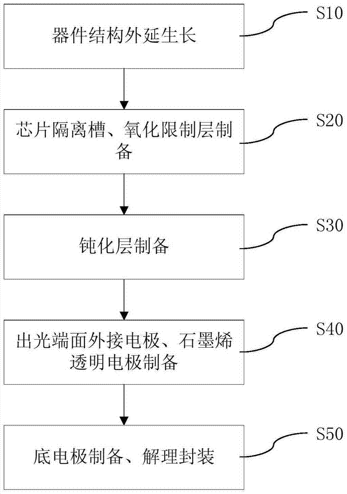
The traditional electrode preparation needs to fill the isolation tank, and realize the conduction of the electrodes on both sides of the isolation tank through metal bridges. However, most of the isolation tank fillers are some organic glues. These glues have poor temperature resistance and large volume changes at high and low temperatures. Large, it is easy to cause the upper bridging metal layer to break, resulting in device failure

Method used


Image

  • Surface emitting laser and preparation method thereof
  • Surface emitting laser and preparation method thereof

Examples


Embodiment Construction

[0023] In order to better illustrate the technical means adopted by the present invention and its effects, a detailed description will be given below in conjunction with the embodiments of the present invention and the accompanying drawings. It will, however, be evident that various changes and modifications can be made to the present invention without departing from the broader spirit and scope of the invention as defined in the appended claims. Therefore, the following examples have an illustrative rather than a limiting meaning.

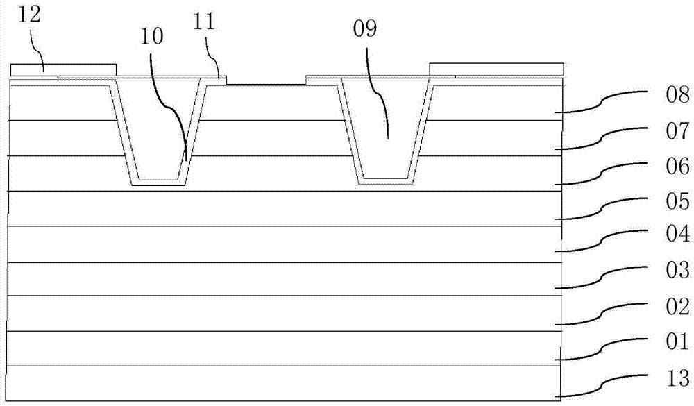
[0024] figure 1 is a schematic cross-sectional structure diagram of a surface-emitting laser according to an embodiment of the present invention.

[0025] refer to figure 1 As shown, the surface emitting laser according to the embodiment of the present invention is bottom electrode 13, substrate 01, lower DBR 02, lower confinement layer 03, active region 04, upper confinement layer 05, oxidation confinement layer 06, The upper DBR 07, the conta...


PUM


Abstract

The invention discloses a surface emitting laser which sequentially comprises a bottom electrode, a substrate, a lower Bragg reflecting mirror, an active region, an oxidation confinement layer, an upper Bragg reflecting mirror, a contact layer and an external electrode from the bottom up. The surface emitting laser is characterized by further comprising isolation grooves, a passivation layer covering the surface of each isolation groove and a contact electrode connected between the contact layer and the external electrode, wherein the isolation groove extends downward from the surface of the contact layer, runs through the upper Bragg reflecting mirror and reaches the oxidation confinement layer, and the contact electrode is a graphene transparent electrode. According to the invention, a graphene material is adopted is prepare the graphene transparent electrode at a light emitting end face, the graphene transparent electrode forms a top electrode together with the external electrode at the light emitting end face so as to replace an existing annular metal electrode, injection of current is realized, and the working stability of the device can be improved. In addition, the graphene transparent electrode has the advantages of high thermal conductivity and electrical conductivity, high mechanical strength, extremely high transmittance and the like.

Description

technical field [0001] The invention relates to the field of lasers, in particular to a surface-emitting laser using graphene as a transparent electrode and a preparation method thereof. Background technique [0002] Vertical Cavity Surface Emitting Laser (VCSEL) has the advantages of low threshold, good wavelength stability, small light divergence angle, high coupling efficiency with optical fiber and easy high-density integration. One of the indispensable and important devices in the field of optoelectronics such as laser display and optical information processing. [0003] Due to the poor light transmittance of metal electrodes, ring-shaped metal electrode structures are generally used in surface-emitting lasers to realize the preparation of light-emitting end-face electrodes. This electrode structure requires multiple photolithographic overlay processes and requires high alignment accuracy. For such an electrode structure, for a small-sized laser chip, the difficulty o...

Claims


Application Information

Patent Timeline
Patent Type & Authority Applications(China)
IPC IPC(8): H01S5/042H01S5/183
CPCH01S5/0425H01S5/183
Inventor 赵勇明孙玉润于淑珍何洋宋焱董建荣
Owner SUZHOU INST OF NANO TECH & NANO BIONICS CHINESE ACEDEMY OF SCI
Why Eureka
Try Eureka