Double-beam laser TIG composite welding process for thin plate butt welding net forming

A hybrid welding, double beam technology, applied in welding/welding/cutting items, welding equipment, manufacturing tools, etc., can solve the problems of bulge, inability to meet the flow channel morphology of active thermal protection components, and spatter on the back of the weld. It can achieve the effect of good formation of the front of the weld, suppressing defects such as back spatter and bulge, and realizing the net shape of the back of the weld.

Inactive Publication Date: 2017-07-14
BEIJING UNIV OF TECH
View PDF4 Cites 13 Cited by
  • Summary
  • Abstract
  • Description
  • Claims
  • Application Information

AI Technical Summary

Problems solved by technology

However, in order to achieve double-sided forming in the welding process of these methods, the weld penetration must be greater than the thickness of the plate, which will cause defects such as splashes and protrusions on the back of the weld, and cannot meet the requirements of the active thermal protection component for the flow channel shape

Method used


Image

  • Double-beam laser TIG composite welding process for thin plate butt welding net forming
  • Double-beam laser TIG composite welding process for thin plate butt welding net forming
  • Double-beam laser TIG composite welding process for thin plate butt welding net forming

Examples


Embodiment 1

[0016] Embodiment 1 welding process parameter is as shown in the table below:

[0017]

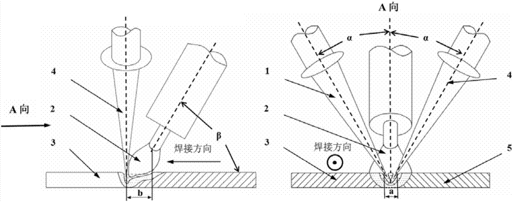
[0018] Among them, P is the laser power, V is the welding speed, I is the arc current, α is the incident angle of the laser beam, β is the inclination angle of the arc, and a is the distance between the focal points of the laser beam; the butt gap is set to 0.2 mm, and the laser beam defocus The distance between the center line of the laser beam 4 and the arc 2 on the workpiece 6 is b=2mm, the shielding gas is Ar gas, and the gas flow rate is 15L / min; during welding, a spatter receiving plate is set at 2 mm from the lower surface of the workpiece, and the surface state after welding is used to represent the degree of back spatter during welding. The material used in this embodiment is a GH3128 thin plate with a thickness of 1 mm. Before welding, use acetone to remove the oil stains on the surface of the workpiece to be welded and the butt surface.

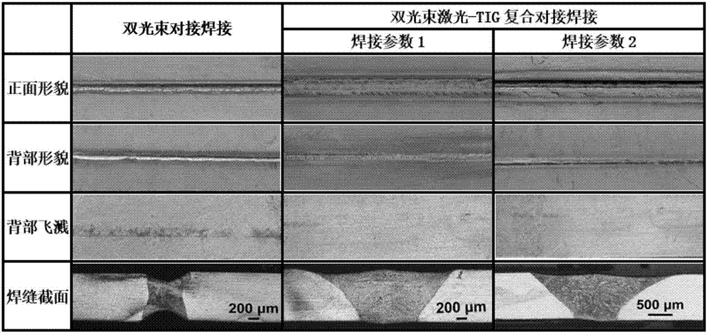
[0019] From the weld surface and cr...

Embodiment 2

[0021] Embodiment 2 Welding process parameters are as shown in the table below:

[0022]

[0023] Among them, P is the laser power, V is the welding speed, I is the arc current, △t is the butt gap; the distance between the laser beam focus is a=1.5mm, the laser beam incident angle α=10°, and the arc inclination β=60° , the defocusing amount of the laser beam is 0mm, the height of the tungsten electrode is H=1.5mm, the extension length of the tungsten electrode is L=5mm; the distance between the center line of the laser beam 4 and the arc 2 on the workpiece 6 is b=2mm, and the protective gas is Ar gas , the gas flow rate is 15L / min; when welding, a spatter receiving plate is set at 2 mm from the lower surface of the workpiece, and the surface state after welding is used to represent the degree of back spatter during welding. The material used in this embodiment is a GH3128 thin plate with a thickness of 2mm. Before welding, use acetone to remove the oil stains on the surface...


PUM

PropertyMeasurementUnit
thicknessaaaaaaaaaa
lengthaaaaaaaaaa
thicknessaaaaaaaaaa

Abstract

The invention discloses a double-beam laser TIG composite welding process for thin plate butt welding net forming, and the double-beam laser TIG composite welding process is suitable for butt welding of a thin plate. A provided welding method is suitable for realizing butt welding net forming of the thin plate under a butt joint clearance condition, and defects such as the sinking, the undercut, the back protrusion and splash which are prone to appear in a butt welding process are overcame. The process is characterized in that a butt welding seam serves as a center, incidence of double laser beams is conducted obliquely, and focuses of the double laser beams are symmetrically distributed on mental base materials at the two sides of the butt clearance; and a centre line of a TIG electric arc is in the same plane as a centre line of the butt welding seam and has a certain angle with a plate face; during the welding, the TIG electric arc is located at the rear side of the perpendicular bisector of the connection line of the focuses of the double laser beams. Compared with the traditional laser butt welding method, the clearance adaptability of the double-beam laser TIG composite welding process for thin plate butt welding net forming is greatly improved in the thin plate butt welding process, the weld width of a welding seam is obviously increased, surface forming and back forming of the welding seam are significantly improved, and the defects of back splash, protrusions and the like are effectively suppressed.

Description

technical field [0001] The invention relates to a new method of thin plate butt welding (under gap condition), which specifically adopts a double-beam laser-TIG composite welding process. The method can realize the net shape welding effect of no undercut on the front side of the thin plate butt welding seam, and no defects such as spatter, undercut and protrusion on the back side, and belongs to the technical field of material processing. Background technique [0002] For the purpose of component cooling and long-term stable work, the main heat-bearing structures such as rocket engine tail nozzles mostly adopt active thermal protection structures with inner flow channels (mainly composed of skin and substrate processed with inner flow channels). Due to the three-dimensional structural characteristics of the skin, the multi-stage tailor welding process is currently used for connection and manufacture. Due to the large size and thin wall of the skin, it is extremely difficult...

Claims


Application Information

Patent Timeline
Patent Type & Authority Applications(China)
IPC IPC(8): B23K28/02B23K101/18
CPCB23K28/02B23K2101/18B23K2101/185
Inventor 肖荣诗陈乐武强
Owner BEIJING UNIV OF TECH
Why Eureka
Try Eureka