Biomass forming fuel solid phase low temperature and gas phase high temperature combustion method and device

A biomass fuel and briquette fuel technology, which is applied in the direction of solid fuel combustion, combustion equipment, lighting and heating equipment, etc., can solve the problems of high emissions, gray fertilizer failure, etc., to reduce pollution, increase combustion temperature, and improve equipment reliability sexual effect

Active Publication Date: 2017-07-14
SHANDONG UNIV OF TECH
View PDF13 Cites 3 Cited by
  • Summary
  • Abstract
  • Description
  • Claims
  • Application Information

AI Technical Summary

Problems solved by technology

[0006] The technical problem to be solved by the present invention is: to overcome the deficiencies of the prior art, and to provide a method to fundamentally solve the problems of coking, slagging, high discharge of gas-solid pollutants, and failure of ash fertilizers in burning e

Method used


Image

  • Biomass forming fuel solid phase low temperature and gas phase high temperature combustion method and device
  • Biomass forming fuel solid phase low temperature and gas phase high temperature combustion method and device
  • Biomass forming fuel solid phase low temperature and gas phase high temperature combustion method and device

Examples


Embodiment 1

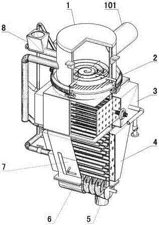
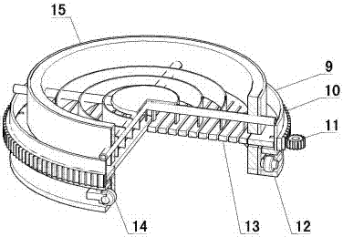
[0045] Such as figure 1 Shown: a biomass briquette fuel solid-phase low-temperature, gas-phase high-temperature combustion device, including a furnace 1, a smoldering area 3 and a cooling area 4 arranged in sequence from top to bottom, the feed port of the smoldering area 3 and the furnace 1 The discharge port is connected, the discharge port of the smoldering zone 3 is connected with the cooling zone 4, the bottom of the furnace 1 is provided with a grate 13, and the grate 13 is provided with a crushing mechanism 2 for crushing materials, and the materials are in the lower part of the furnace 1 Drying and pyrolysis, the grate 13 is connected with a rotating mechanism to disturb the biomass fuel, and make the carbon powder fall into the smoldering area 3 for smoldering, and at the same time move the block biomass fuel to the middle of the grate 13, and the crushing mechanism 2 The blocky biomass fuel is broken into carbon powder and then falls into the smoldering zone 3 for sm...

Embodiment 2

[0081] Such as Figure 12 Shown: the difference between embodiment 2 and embodiment 1 is: the smoldering pool air intake box 25 includes the smoldering pool combustion-supporting box and the smoldering pool cooling box, and the smoldering pool cooling box and the smoldering pool combustion-supporting box are set independently. Air inlet pipe 27 comprises combustion-supporting air inlet pipe 41 and cooling air inlet pipe 42, and combustion-supporting air inlet pipe 41 and cooling air inlet pipe 42 are all arranged in the smoldering pool 20, and the right end of combustion-supporting air inlet pipe 41 and the smoldering pool combustion-supporting The box is communicated, and the right end of the cooling air inlet pipe 42 is communicated with the cooling tank of the smoldering pool. The left ends of the combustion-supporting air inlet pipe 41 and the cooling air inlet pipe 42 are all communicated with the gas outlet box 28 of the smoldering pool. The combustion-supporting air in...


PUM

PropertyMeasurementUnit
Particle sizeaaaaaaaaaa

Abstract

The invention provides a biomass forming fuel solid phase low temperature and gas phase high temperature combustion method and device and belongs to the technical field of biomass combustion. The biomass forming fuel solid phase low temperature and gas phase high temperature combustion method is characterized by comprising the following steps that (1) biomass fuel is dried and pyrolyzed into coal, and gas produced by drying and pyrolyzing is combusted on the upper portion of the biomass fuel; (2) the pyrolyzed biomass fuel is crushed into coal powder with the particle size not larger than 3 mm and is accumulated; (3) the coal powder is smoldered into ash, the smoldering temperature is not higher than 650 DEG C, and incompletely-combusted gas produced by smoldering is transported to the upper portion of the biomass fuel to be combusted; and (4) the ash is discharged after being cooled. The biomass forming fuel solid phase low temperature and gas phase high temperature combustion method solves the problems that for combustion equipment of straw and other agricultural waste, coking and slagging occur, gas and solid pollutant emission is high, and ash fertilizers lose efficacy from the source. The biomass forming fuel solid phase low temperature and gas phase high temperature combustion device adapts to small and medium-sized combustion equipment.

Description

technical field [0001] The invention discloses a solid-phase low-temperature, gas-phase high-temperature combustion method and device for biomass briquette fuel, belonging to the technical field of biomass combustion. Background technique [0002] With the adjustment of my country's agricultural structure and the development of rural economy, it is urgent to solve the problem of distributed small-scale heating such as drying of agricultural products and heating of agricultural facilities. For example: my country's grain drying mechanization level is 10% (the level of 80-90% in Japan and South Korea), and the loss of wet grain mildew is as high as 5% (less than 1% in developed countries). There is an urgent need to develop drying machinery and its matching small and medium-sized heating devices (generally less than 2.8MW). The heating demand of agricultural facilities (livestock and poultry houses, greenhouses, etc.) in 2 / 3 of my country's land area is also extremely urgent....

Claims


Application Information

Patent Timeline
IPC IPC(8): F23B90/06
CPCF23B90/06
Inventor 何芳张毅徐攀高振强杨彬彬孙鹏
Owner SHANDONG UNIV OF TECH
Why Eureka
Try Eureka