A kind of drainage device and drainage device prefabricated

A drainage device and drainage ditch technology, which is applied in drainage, safety devices, mining equipment, etc., can solve problems such as poor drainage, water overflow, and inability to solve mine drainage ditch mud cleaning well, so as to quickly clean up mud and liberate Labor force, the effect of reducing human and material resource expenditure

Active Publication Date: 2018-11-16
CHINA UNIV OF MINING & TECH (BEIJING)
View PDF6 Cites 0 Cited by
  • Summary
  • Abstract
  • Description
  • Claims
  • Application Information

AI Technical Summary

Problems solved by technology

More importantly, because the mesh structure of the drainage device can only allow water to pass through, it will not speed up the flow of water flow. When the silt continues to accumulate in front of the mesh and the mesh is blocked, it will cause poor drainage, and even work. The phenomenon of water overflow in the surface and roadway
It can be seen that the existing mine drainage structure cannot well solve the goal of mine drainage ditch silt cleaning

Method used


Image

  • A kind of drainage device and drainage device prefabricated
  • A kind of drainage device and drainage device prefabricated
  • A kind of drainage device and drainage device prefabricated

Examples


Embodiment 1

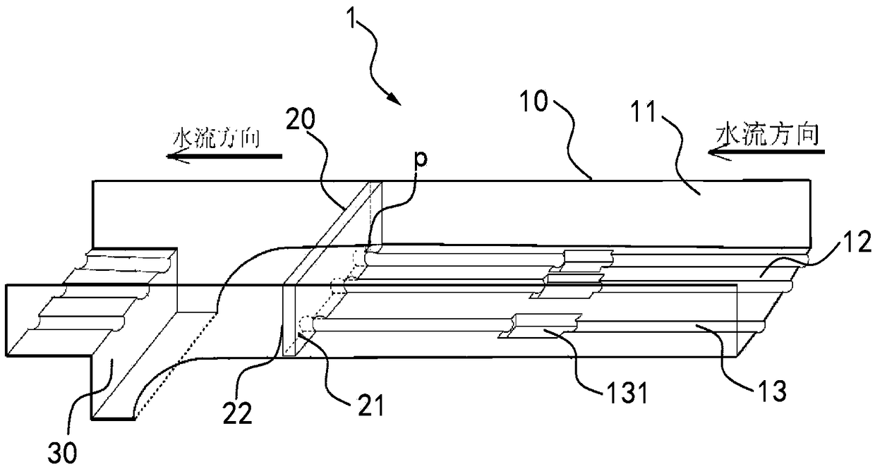
[0046] combine figure 1 Let's look at Example One. In the drainage device 1 shown in Embodiment 1, the arrows indicate the direction of water flow, and upstream and downstream are defined according to the direction of water flow. The drainage device 1 comprises a drainage ditch 10 and at least one baffle 20 arranged in the drainage ditch, and the baffle 20 defines an upstream side 21 and a downstream side 22 according to the direction of water flow. The drainage ditch 10 includes two sidewalls 11 and a bottom surface 12, wherein the connection between the bottom surface 12 and the two sidewalls 11 is set as a circular arc transition surface. Wherein, three lower notches 23 are provided on the lower end side of the baffle plate 20, and these three lower notches 23 are set as semicircles in this embodiment. The bottom surface 12 of the drainage ditch is provided with three water guide grooves 13 along the length direction of the water drainage ditch 10. The water guide grooves...

Embodiment 2

[0058] Such as Figure 8 shown. In the second embodiment, on the basis of the first embodiment, a silt storage frame 8 is placed in each sedimentation pit 30 . The mud storage frame 8 has several drainage holes 81 for collecting slag. When the slag is deposited to a certain thickness, the silt storage frame 8 is proposed, and the drain hole 81 can remove water, reduce the weight of slag in the silt storage frame 8, and save manpower, which is more convenient and efficient than the first embodiment. The sludge storage frame 8 also has a handle 82 . Silt storage frame 8 can adopt durable plastic material, can resist corrosion and reduce self weight.

Embodiment 3

[0059] Embodiment three such as Figure 9 Shown is the structural representation of embodiment three. In the third embodiment, two or more components of the drainage device 1 in the first embodiment are manufactured together to form a prefabricated module 9 . The groove body of the prefabricated module 9 can be made of metal, plastic or composite material. In this embodiment, fiber-reinforced composite material is used as an example, and integral molding can be selected to form the bottom surface structure at one time. In a specific example, the bottom surface 12 and the side wall 11 of the prefabricated module 9 can be formed of glass fiber reinforced plastics, which can take full advantage of its advantages of low cost and high strength, and is easy to mass produce.

[0060] When in use, the prefabricated module 9 can be directly placed in the original mine tunnel. The bottom surface 12 and the two side walls 11 of the drainage device 1 of each monomer of the prefabricated...


PUM


Abstract

The invention provides a water draining device and a prefabricated member of the water draining device. The water draining device and the prefabricated member of the water draining device are arranged in a water draining ditch of the base side of a mine lot roadway. The water draining device comprises at least one baffle and at least one sedimentation pit which are arranged in the water draining ditch; the baffles can enclose a water flow in the water draining ditch, and at least one water guiding passageway is formed between the peripheries of the baffles and the water draining ditch. Before the baffles are washed open by water pressure, the water flow in the water draining ditch is desludged trhough the water guiding passageways, and sediments in the water guiding passageways are washed into the sedimentation pits; and when the water flow of the side faces of the upper streams of the baffles are accumulated to a certain height, the baffles are opened by the raised water pressure to enable water accumulated on the side faces of the upper streams of the baffles to be momentarily released out, and thus the sediments on the positions, at the lower streams of the baffles, of the bottom surface of the water draining ditch are washed into the sedimentation pits. The water draining device has the effect that sludge sedimentated on the bottom surface of the water draining ditch is automatically cleared away and impacted.

Description

technical field [0001] The invention relates to the technical field of mining safety, in particular to a mine drainage device and a prefabricated part of the drainage device, which have smooth drainage and are convenient for clearing mud at fixed points. Background technique [0002] With the mining of the coal mine face and the extension of the roadway, the falling slag and gravel will fall in the mine drainage ditch. The existing drainage ditches cannot be cleaned quickly and automatically, which often causes problems such as congestion of the drainage ditches and poor drainage, and the drainage capacity is limited, resulting in water overflow in the working face and roadways, which is not conducive to the safe production of coal mines, let alone Conducive to maintaining a relatively comfortable working environment. [0003] In order to prevent these problems from happening, the working face and the roadway have to clean up the silt in the ditch from time to time. The cur...

Claims


Application Information

Patent Timeline
Patent Type & Authority Patents(China)
IPC IPC(8): E21F16/00
CPCE21F16/00
Inventor 杨晓杰刘晨康侯定贵王二雨郝振立胡超文王嘉敏
Owner CHINA UNIV OF MINING & TECH (BEIJING)
Why Eureka
Try Eureka