Centrifugal moving impeller, blade assembly and fan

A technology of centrifugal blades and moving impellers, applied in the field of fan impellers and fluid impeller machinery, can solve the problems of uneven air outlet, small air outlet, large resistance, etc., and achieve the effect of uniform air flow, stable air flow and small disturbance

Pending Publication Date: 2017-07-28
SHANGHAI LANGQIN INVESTMENT MANAGEMENT
View PDF6 Cites 2 Cited by
  • Summary
  • Abstract
  • Description
  • Claims
  • Application Information

AI Technical Summary

Problems solved by technology

However, since it adopts the form of axial flow impeller (that is, the axial flow fan blade in the invention patent) + axial guide vane (that is, the axial flow fan stator blade in the invention patent), it is found that this However, the wind pressure it can achieve is still not enough to completely overcome the resistance of the filter layer (such as the filter cotton used in practice), especially when the haze is severe, tiny particles will The filter layer will be blocked quickly and the resistance will be greater, and the efficiency of the fan in this form is low
[0004] A general and usual method to solve the above problem of insufficient air pressure is to use the air outlet volute to boost the pressure. The fan installed with the air outlet volute can achieve a higher wind pressure. However, due to the uneven circumferential shape of the air outlet volute, the air outlet If it is small, it will lead to insufficient air flow and uneven air outlet around the outlet, and will make the working range of the fan narrow, low efficiency, and high energy consumption. In this case, the power capacity of the air purifier must be increased accordingly when wearing the head. Not only increases the cost, but also increases the weight of the purifier and affects the consumer experience

Method used


Image

  • Centrifugal moving impeller, blade assembly and fan
  • Centrifugal moving impeller, blade assembly and fan
  • Centrifugal moving impeller, blade assembly and fan

Examples


Embodiment

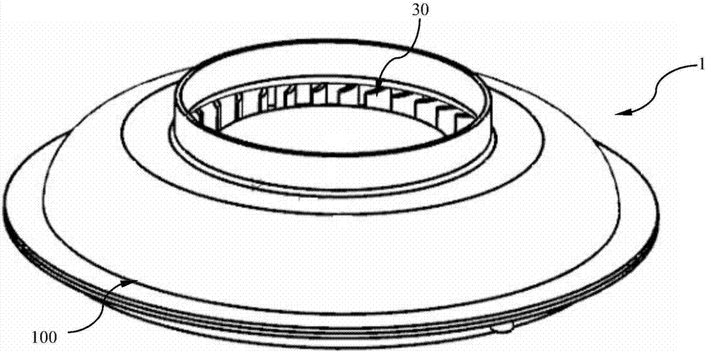
[0034] figure 1 It is a three-dimensional schematic diagram of the fan of the present invention.

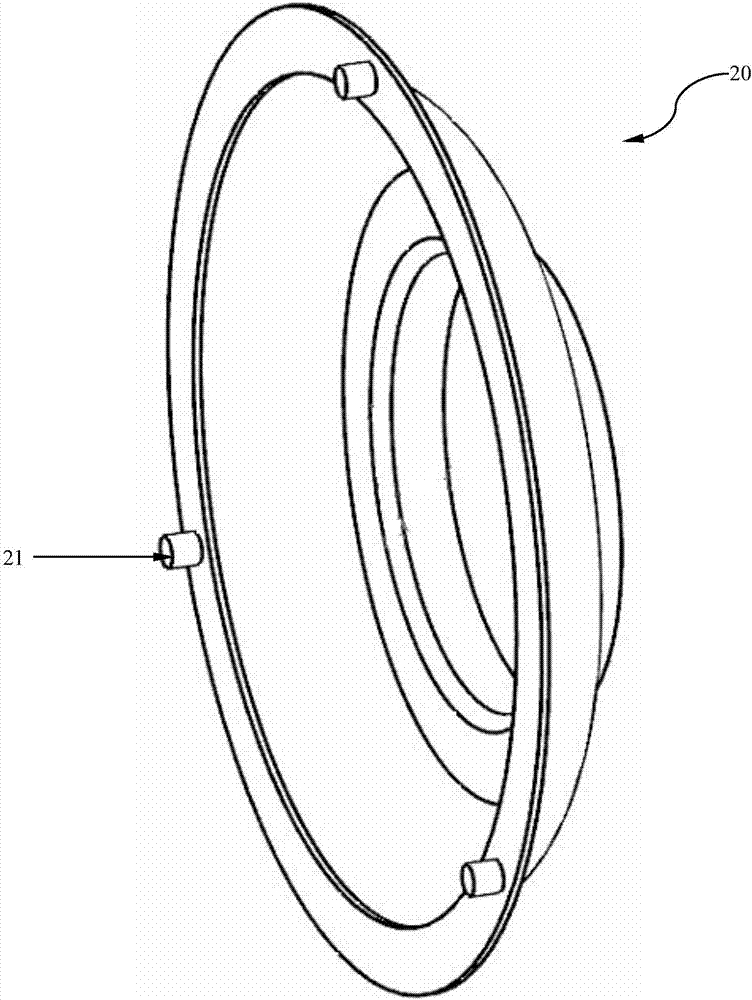
[0035] figure 2 for figure 1 view from the other direction.

[0036] image 3 It is a sectional view of the fan of the present invention.

[0037] Figure 4 for image 3 view from the other direction.

[0038] Such as Figure 1-4 As shown, the fan 1 includes a prime mover (not shown in the figure) and a blade assembly 100, and the output shaft of the prime mover is connected to the blade assembly. In this embodiment, the fan is a small fan suitable for head-mounted air purifiers. Correspondingly, the prime mover is a permanent magnet DC motor, and its stator is a coil, and the rotating part is a magnet shell (which is used by the cooling fan of the cpu of a personal computer. micro motor).

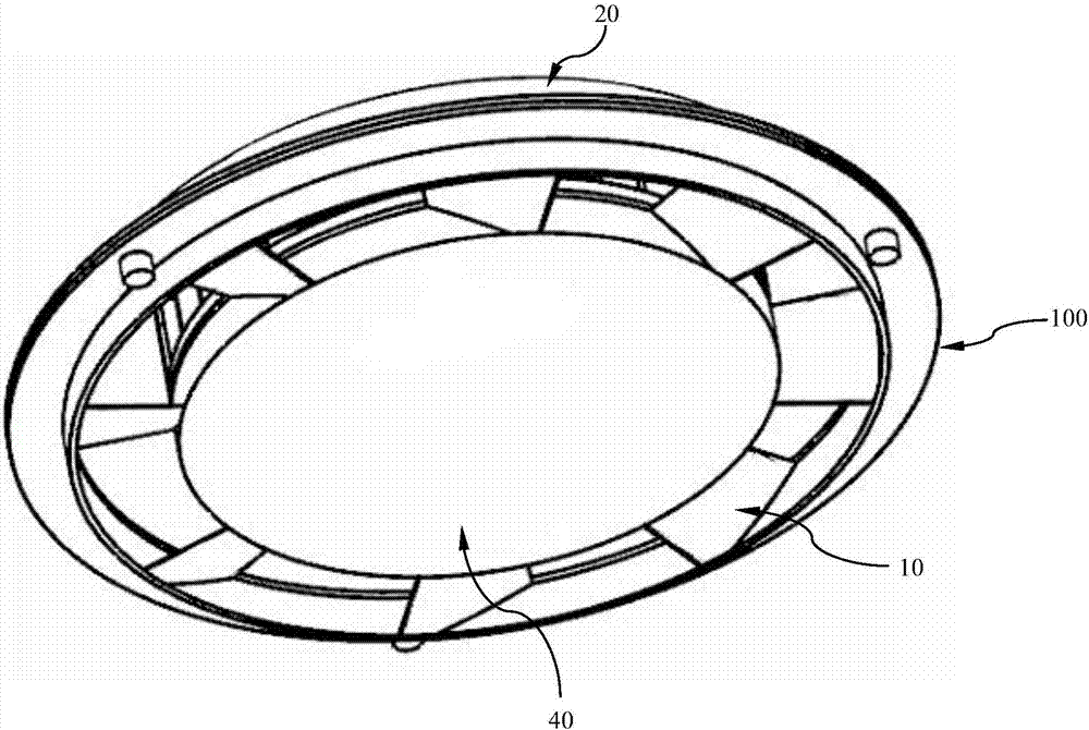
[0039] Such as figure 2 , 3 As shown in , 4 , the blade assembly 100 includes an axial guide vane 10 , an annular cover 20 , a centrifugal impeller 30 and a rear cover 40 .

[...


PUM


Abstract

The invention discloses a centrifugal moving impeller, a blade assembly and a fan. The centrifugal moving impeller, the blade assembly and the fan are characterized in that the impeller comprises an annular pedestal and a plurality of centrifugal blades which are arranged on at least one face of the annular pedestal in an encircling mode; the centrifugal blades are arc-shaped blades of the same height and the same thickness; the ends, close to the inner ring face of the annular pedestal, of the centrifugal blades are provided with inlet ends, and the ends, close to the outer ring face of the annular pedestal, of the centrifugal blades are provided with outlet ends; and the angles of contingence of the centrifugal blades are linearly and evenly increased from the inlet ends to the outlet ends. Inhaled gas is used for acting through high-speed rotation of the multiple centrifugal blades so as to convey the gas into high-speed flowing gas, the gaps between the adjacent centrifugal blades are bigger and bigger along with the flowing direction of airflow, and therefore kinetic energy of the air flowing at a high speed can be converted into high-pressure potential energy in the flowing process, and the air flowing at the high speed can obtain high pressure after flowing out of the gaps. Moreover, due to the fact that the gaps are gradually increased, the airflow is quite stable, corresponding disturbance in the high-speed rotating process is quite small, and the airflow is made evener.

Description

technical field [0001] The invention relates to an impeller, in particular to an impeller of a fan, and belongs to the field of fluid impeller machinery. Background technique [0002] In the head-mounted air purifier that actively sucks air to filter, it is necessary to use a fan to suck air into the air filter layer for air filtration, and the filtered air is supplied to people's mouth and nose for breathing. [0003] Although Tang Binhong's (Chinese patent, axial flow fan for masks and masks thereof, CN205446182U, open day 2016.08.10) designed axial flow fans has stronger wind power than ordinary fans, it can overcome the resistance of the filter layer and is convenient for children with difficulty breathing. Elderly and frail elderly wear air purifiers. However, since it adopts the form of axial flow impeller (that is, the axial flow fan blade in the invention patent) + axial guide vane (that is, the axial flow fan stator blade in the invention patent), it is found that ...

Claims


Application Information

Patent Timeline
Patent Type & Authority Applications(China)
IPC IPC(8): F04D29/28F04D29/30F04D29/44F04D25/08
CPCF04D25/0606F04D25/08F04D29/281F04D29/30F04D29/441
Inventor 汤斌洪
Owner SHANGHAI LANGQIN INVESTMENT MANAGEMENT
Why Eureka
Try Eureka