
A circular stepped magnetic biofilm reactor

A biofilm reactor and stepped technology, applied in the field of water treatment, can solve the problems of increased cost of filler, shortened operation cycle, and reduced reactor processing efficiency, so as to realize resource utilization, improve operating performance, and extend system operating cycle Effect

Active Publication Date: 2020-07-31
JIANGSU UNIV
View PDF4 Cites 0 Cited by
  • Summary
  • Abstract
  • Description
  • Claims
  • Application Information

AI Technical Summary

Problems solved by technology

[0003] However, during the operation of the biofilter, it is often necessary to supplement, replace regularly, and backwash due to the loss and blockage of the filter material, resulting in an increase in the cost of the filler, shortening the operating cycle of the system to varying degrees, and reducing the treatment efficiency of the reactor.

Method used


Image

  • A circular stepped magnetic biofilm reactor
  • A circular stepped magnetic biofilm reactor
  • A circular stepped magnetic biofilm reactor

Examples


Embodiment 1

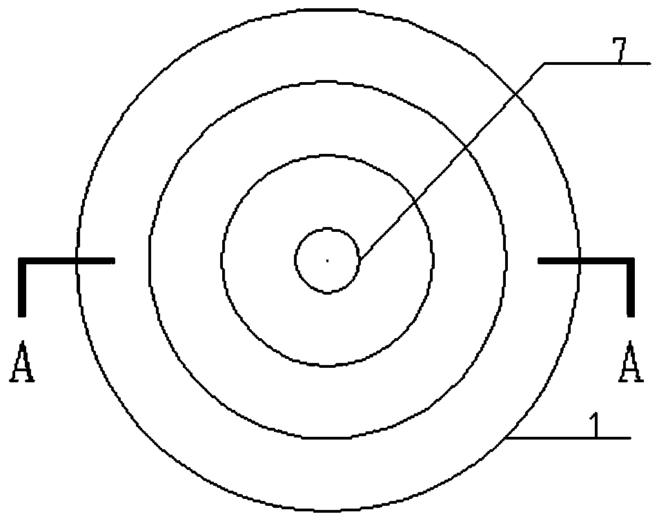
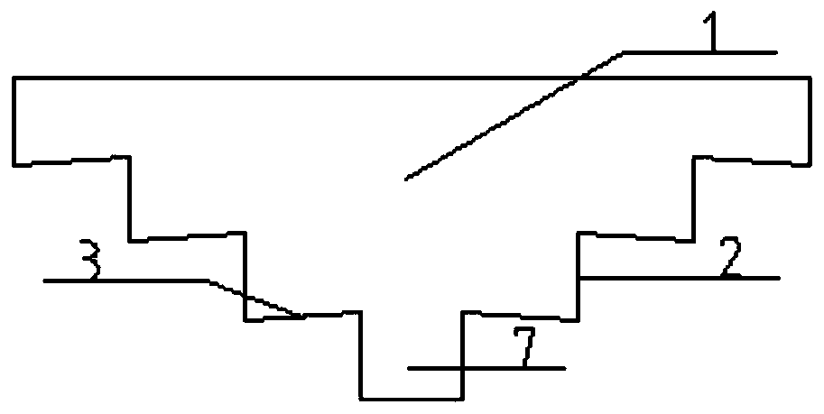
[0041] Such as figure 1 with figure 2 As shown, a circular stepped magnetic biofilm reactor includes a circular stepped housing 1, a water outlet pipe 7 and a magnetic composite carrier. The circular stepped housing 1 is composed of a plurality of groups of hollow cylinders 2 and rings 3 of different sizes. The diameter of the hollow cylinder 2 and the inner and outer diameters of the ring 3 decrease from top to bottom. In each group of hollow cylinder 2 and ring 3, the inner wall of the bottom end of the hollow cylinder 2 and the outer edge of the ring 3 are connected together by welding.

[0042] In each group of hollow cylinder 2 and ring 3, the hollow cylinder 2 is made of stainless steel, the wall thickness is 5mm, and the height is 500mm; the ring 3 is made of stainless steel, the thickness is 5mm, and the outer diameter is the same as that of the hollow cylinder. The inner diameter of 2 is the same, and the difference between the outer diameter of the ring 3 and the inner...

Embodiment 2

[0055] A circular stepped magnetic biofilm reactor includes a circular stepped shell 1, a water outlet pipe 7 and a magnetic composite carrier. The circular stepped housing 1 is composed of a plurality of groups of hollow cylinders 2 and rings 3 of different sizes. The diameter of the hollow cylinder 2 and the inner and outer diameters of the ring 3 decrease from top to bottom. In each group of hollow cylinder 2 and ring 3, the inner wall of the bottom end of the hollow cylinder 2 and the outer edge of the ring 3 are connected together by glue.

[0056] In each group of hollow cylinder 2 and ring 3, the hollow cylinder 2 is made of plexiglass with a wall thickness of 10mm and a height of 800mm; the ring 3 is made of plexiglass with a thickness of 10mm and an outer diameter of The inner diameter of the hollow cylinder 2 is the same, and the difference between the outer diameter of the ring 3 and the inner diameter of the ring 3 is 1600 mm. The inner edge of the ring is slightly h...


PUM

PropertyMeasurementUnit
particle sizeaaaaaaaaaa
thicknessaaaaaaaaaa
heightaaaaaaaaaa

Abstract

The invention provides a round step type magnetic bio-membrane reactor, which comprises a round step type casing, a water outlet pipe and a magnetic compound carrier. The round step type casing is composed of a plurality of groups of different-sized hollow columns and rings, and the diameters of the hollow columns and the inner and outer diameters of the rings sequentially decrease from top to bottom; in each group of hollow column and ring, an inner wall of the bottom end of the hollow column and the outer edge of the ring are connected together through welding or bonding. As a plurality of groups of hollow columns and rings are utilized in the biological reactor, the problem that a traditional biological filter is prone to being plugged by filter materials is solved, times for replacing and cleaning filter materials are reduced, a system operation period is prolonged, and processing efficiency of the reactor is further improved. As the hollow column-shaped magnetic compound carrier is arranged in the biological reactor, filter material loss is effectively reduced, a using period of the filter materials is delayed, and system operation cost is reduced.

Description

Technical field [0001] The invention belongs to the technical field of water treatment, and relates to a biofilm reactor, in particular to a circular stepped magnetic biofilm reactor. Background technique [0002] The biological filter process draws on the design principles of biological contact oxidation and feed water filtration. The granular fillers in the filter such as ceramsite, coke, quartz sand, activated carbon, etc. are used as the carrier, and the inside of the filter is aerated to filter A large number of biofilms grow on the surface of the material. When the water to be treated flows through, the biological metabolism of microorganisms, bioflocculation, physical adsorption and retention of biofilms and fillers, and the hierarchical predation of the food chain along the direction of the water flow in the reactor are used to achieve Efficient removal of pollutants, while taking advantage of the existence of aerobic and anoxic areas in the reactor to achieve the functio...

Claims


Application Information

Patent Timeline
Patent Type & Authority Patents(China)
IPC IPC(8): C02F3/34
CPCC02F3/34C02F3/342C02F2101/16
Inventor 刘巧赵如金许丽霞卢露朱凡徐成飞龚丽影朱海东
Owner JIANGSU UNIV
Learn More