
Die for rotary swaging machine and manufacturing method of die

A technology for rotary forging machines and molds, which is used in the manufacture of tools, forging/pressing/hammering machinery, forging/pressing/hammer devices, etc. It can solve the problems of unreasonable mold structure, high cost, low efficiency, etc. The effect of toughness and roughness, low production efficiency, and complete and smooth surface

Inactive Publication Date: 2017-08-11
NORTHWEST INSTITUTE FOR NON-FERROUS METAL RESEARCH
View PDF5 Cites 3 Cited by
  • Summary
  • Abstract
  • Description
  • Claims
  • Application Information

AI Technical Summary

Problems solved by technology

The mold structure is simple, and a layer of surfacing layer is arranged on the inner wall of the mold hole. The surfacing layer is formed by surfacing with high-performance mold manufacturing materials. The surfacing layer has high strength, high toughness, high fatigue resistance and It improves the swaging performance of the working surface in the die hole, solves the problems of unreasonable die structure, low performance, high cost, low efficiency, and poor precision of the existing dies used in swivel forging machines, and improves the use of swivel forging machines. Improve the performance of the mold, shorten the swaging manufacturing cycle, reduce the amount of high-performance and expensive mold materials, and significantly reduce the manufacturing cost

Method used


Image

  • Die for rotary swaging machine and manufacturing method of die
  • Die for rotary swaging machine and manufacturing method of die
  • Die for rotary swaging machine and manufacturing method of die

Examples


Embodiment 1

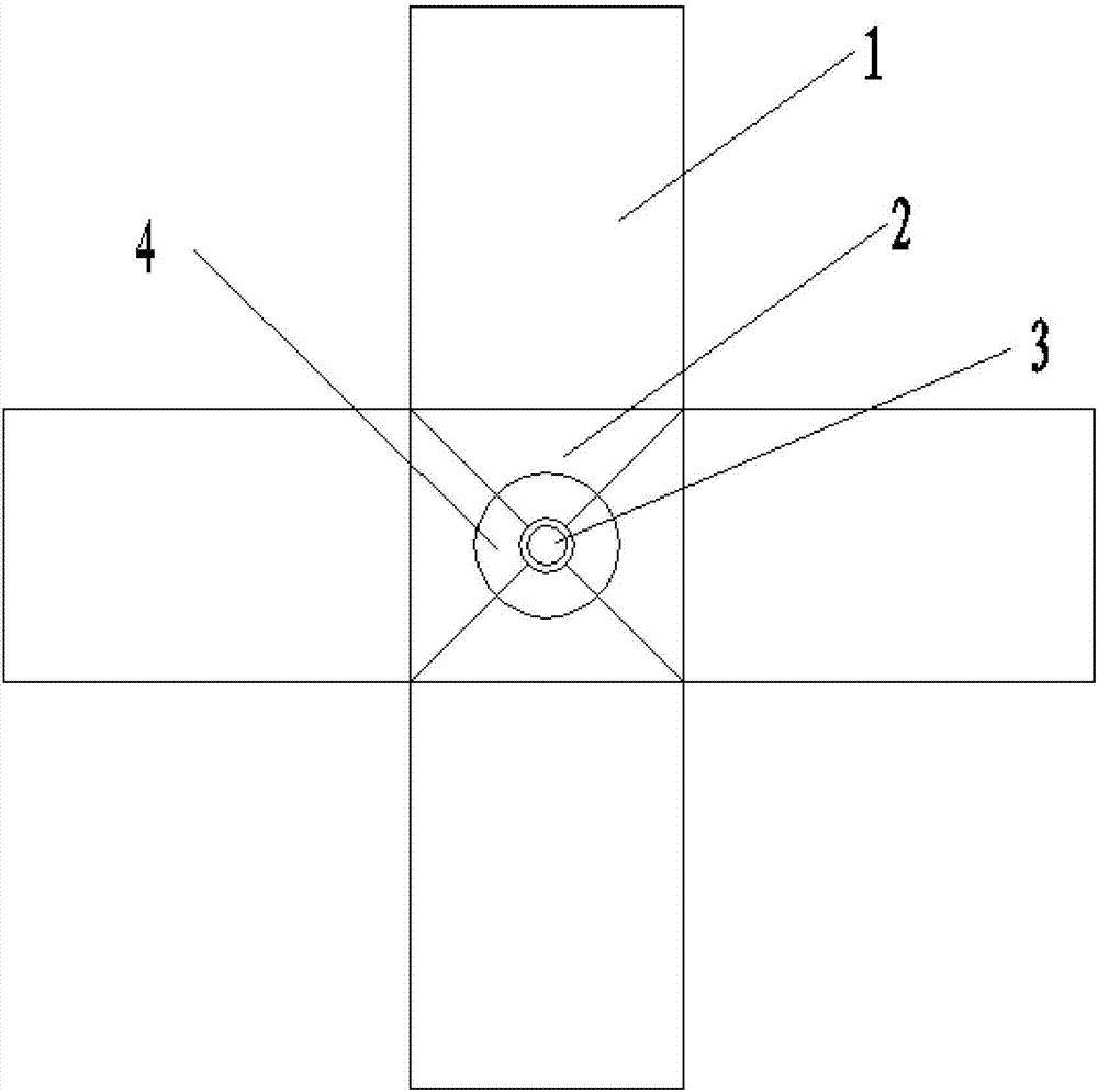
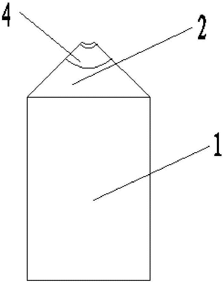
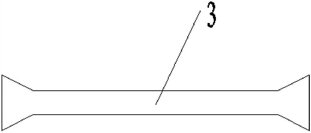
[0028] Such as figure 1 , figure 2 and image 3 As shown, this embodiment includes a mold main body, which is assembled sequentially by a plurality of mold blocks along the circumferential direction, and the mold blocks include a support body 1 and a working body 2, and the working body 2 of each mold block Assemble to form the working area of ​​the mold main body, the center of the working area of ​​the mold main body is provided with a mold hole 3, the inner wall of the mold hole 3 is provided with a surfacing layer 4, and the inner wall of the surfacing layer 4 The surface is the working surface of the swaging machine for swaging workpieces. The die hole 3 is a circular through hole. The problem that it is difficult to put the billet and tube billet into the mold hole improves the processing efficiency.

[0029] In this embodiment, the material of the working body 2 is cobalt-chromium-tungsten alloy or cobalt-chromium-molybdenum alloy; the material of the support body 1...

Embodiment 2

[0036] Such as figure 1 , figure 2 and image 3 As shown, taking four mold blocks assembled into a mold as an example, the manufacturing method of a mold for a rotary forging machine includes the following steps:

[0037] Step 1, mold blank processing: the mold steel is machined into the support body 1 and the working body 2 of the basic sample blank of the swaging mold, and then surfacing welding is formed on the support body 1 to form a surfacing layer 4; the cross section of the support body 1 is Rectangular, the section of the working body 2 is triangular, and the thickness of the support body 1 and the working body 2 is 30mm;

[0038] Step 2, preliminary processing: the surfacing layer 4 that obtains in step 2 is first through machining milling and grinding, and then assembled into the mold body of the unprocessed mold hole (such as Figure 4 shown);

[0039] Step 3, finishing: use wire cutting to cut out the mold hole 3 in the surfacing layer at the center of the wo...


PUM

PropertyMeasurementUnit
Thicknessaaaaaaaaaa
Roughnessaaaaaaaaaa
Thicknessaaaaaaaaaa

Abstract

The invention discloses a mold for a rotary forging machine, which comprises a mold main body. The mold main body is sequentially assembled from a plurality of mold blocks along the circumferential direction. The mold blocks include a support body and a working body, and the working bodies of each mold block are assembled to form a mold. In the working area of ​​the main body, a mold hole is opened at the center of the working area of ​​the mold body, and a surfacing layer is provided on the inner wall of the mold hole. The inner surface of the surfacing layer is the working surface of the swaging machine for swaging the workpiece. The material of the welding layer is cobalt-chromium-tungsten alloy or cobalt-chromium-molybdenum alloy; the mold hole is a circular through hole, and the ports on both sides of the mold hole expand outward and have a conical structure. In addition, the invention also provides a method for manufacturing the mold. The invention has a simple structure, and a layer of high-strength, high-strength, high-toughness, high-fatigue resistance and high-wear-resistant surfacing layer is provided on the inner wall of the mold hole, so as to improve the usability of the mold for the swaging machine, shorten the swaging manufacturing cycle, Reduce the amount of high-performance expensive mold materials and significantly reduce manufacturing costs.

Description

technical field [0001] The invention belongs to the technical field of molds for rotary forging machines, and in particular relates to a mold for rotary forging machines and a manufacturing method thereof. Background technique [0002] Rotary forged forgings have the advantages of dense structure, high bending strength (additional compressive stress exists on the surface of the forging), smooth surface, high roughness precision (beneficial for parts assembly), and easy cutting (forgings have continuous fiber streamlines). Rotary forging is a very effective processing method for preparing difficult-to-deform alloy wires, rods and pipes. [0003] Rotary forging die is a key component of rotary forging press (swivel forging machine), and its performance, service life, manufacturing cost, production cycle, etc. have an important impact on the production efficiency and production cost of materials. [0004] At present, the structure, material, and production and processing of sw...

Claims


Application Information

Patent Timeline
IPC IPC(8): B21J13/02B23P15/24
CPCB21J13/02B23P15/24
Inventor 张科张文强郑晶贾志华
Owner NORTHWEST INSTITUTE FOR NON-FERROUS METAL RESEARCH
Learn More