
Septic tank treatment device

A technology of septic tanks and stirring devices, which is applied in the direction of anaerobic digestion treatment, biological sludge treatment, chemical instruments and methods, etc., can solve the problems of septic tank silt cleaning and difficulties, achieve the reduction of solid feces, and facilitate operation , the effect of reducing and exempting the clearing

Active Publication Date: 2017-08-11
赣州众顺环保容器设备有限公司
View PDF11 Cites 1 Cited by
  • Summary
  • Abstract
  • Description
  • Claims
  • Application Information

AI Technical Summary

Problems solved by technology

[0004] In view of this, the purpose of the present invention is to provide a septic tank treatment device aimed at the deficiencies of the prior art, which solves the technical problems of severe silt and difficult cleaning of the septic tank, and can evenly inject biodegradants to quickly realize the septic tank treatment. Decomposition of septic tank sewage and sediments, reduction of cleaning, reduction of pollution, and avoidance of dangerous gas accidents

Method used


Image

  • Septic tank treatment device
  • Septic tank treatment device
  • Septic tank treatment device

Examples


Embodiment 1

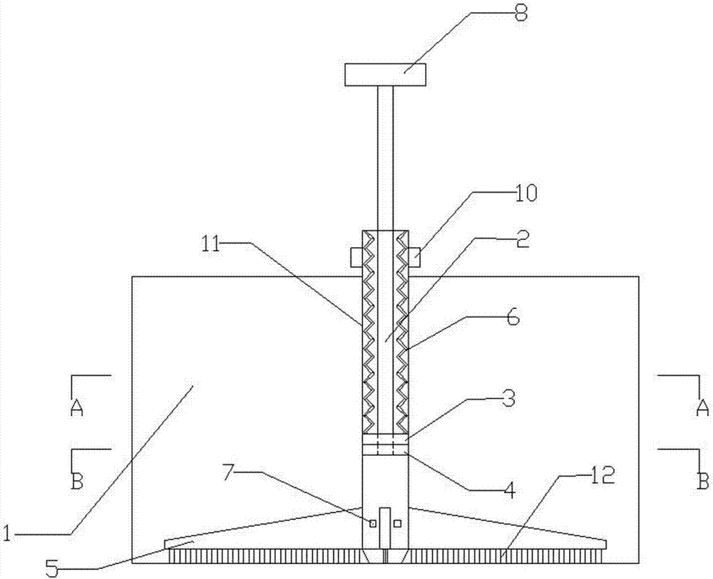
[0033] A septic tank treatment device, set in the septic tank 1, including a liquid adding device and a stirring device;

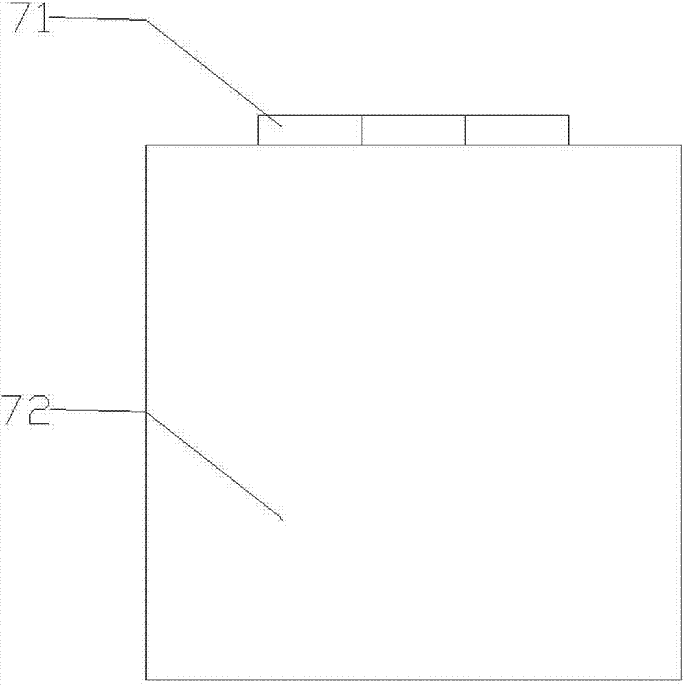
[0034] Such as figure 1 As shown, the liquid adding device includes a piston cylinder 11, a hinge piece 7, a piston and a rebound member 6; as image 3 As shown, the hinge piece 7 includes a spring hinge 71 and a sheet body 72;

[0035] Such as figure 1 As shown, the piston includes a piston handle 8, a piston rod 2 and a piston head; as Figure 6 As shown, the piston head includes a base 3 and a rubber head 4; the rubber head 4 is fixed on the bottom of the base 3;

[0036] The lower part of the piston cylinder 11 is provided with a liquid outlet hole, the hinge piece 7 is fixed on the outer wall of the piston cylinder 11 through the spring hinge 71, the sheet body 72 is sealed and pressed on the liquid outlet hole, and the hinge piece 7 is in a constant state under the elastic force of the spring hinge 71. closed state;

[0037] A through hole is pr...

Embodiment 2

[0045] The difference between this embodiment and Embodiment 1 is that the slide bar 13 extends to the entire height of the piston barrel 11 .

Embodiment 3

[0047] The difference between this embodiment and Embodiment 1 is that the slide bar 13 extends to the stroke height of the piston head in the piston cylinder 11 .


PUM


Abstract

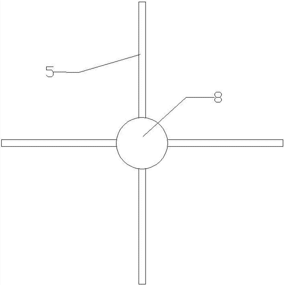
The invention discloses a septic tank treatment device. The septic tank treatment device comprises a liquid adding device and a stirring device, wherein the stirring device comprises a driving disc and a stirring paddle, and the stirring paddle is fixed on the outer wall of a piston barrel; the liquid adding device comprises the piston barrel, a hinge piece, a piston and a rebounding piece; the piston comprises a piston handle, a piston rod and a piston head; the piston head comprises a base and a rubber head; the hinge piece is fixed on the outer wall of the piston barrel by virtue of a spring hinge, and a liquid outlet hole is formed in the lower part of the piston barrel; a through hole is formed in the center of the top of the piston barrel, and the piston handle is fixed at the top of the piston rod; the piston head is fixed at the lower part of the piston rod by virtue of a screw thread; the upper end of the rebounding piece is fixed at the top of the piston barrel, and the lower end of the rebounding piece is fixed on the upper part of the base; and a sliding chute is formed in each of the base and the rubber head, and a sliding bar is arranged on the inner wall of the piston barrel. The septic tank treatment device disclosed by the invention has the advantages that a biological decomposing agent can be uniformly put into a septic tank, decomposition of sewage and sediments of the septic tank is rapidly realized, cleaning is reduced and eliminated, pollution is reduced, and a hazardous gas accident is avoided.

Description

technical field [0001] The invention relates to the technical field of sewage treatment, in particular to a septic tank treatment device. Background technique [0002] Septic tanks generally exist in cities and rural areas, but domestic management of septic tanks is not perfect. According to our country's practice, the sludge cleaning cycle is generally designed to be 3 to 12 months, but the sludge cleaning cycle of many septic tanks is much longer than this, ranging from 3 years to 5 years. No one asked, so that it caused a blockage. If the septic tank is not cleared in time, some precipitated particles rise together with the air bubbles, resulting in a large amount of suspended solids in the clarified sewage, which reduces the removal rate of suspended solids (SS). The long-term accumulation of sediment will inevitably reduce the effective water volume of the septic tank and reduce the residence time of sewage. Sometimes the sewage is discharged out of the septic tank du...

Claims


Application Information

Patent Timeline
Patent Type & Authority Applications(China)
IPC IPC(8): C02F11/04C02F3/34C02F3/28
CPCC02F3/28C02F3/34C02F3/348C02F11/04
Inventor 张花枝
Owner 赣州众顺环保容器设备有限公司
Learn More