Stress-relief annealing technology for steel bearing retainer
A technology for stress-relieving annealing and bearing cages, used in manufacturing tools, heat treatment equipment, furnaces, etc., can solve the problems of low overall strength of the cage, poor plastic toughness of the cage, and high surface stress, and achieve high strength and eliminate residual stress. , The effect of high machining accuracy
- Summary
- Abstract
- Description
- Claims
- Application Information
AI Technical Summary
Problems solved by technology
Method used
Image


Examples
specific Embodiment approach 1
[0017] Specific implementation mode one: combine Figure 1~4 Describe this embodiment, a kind of steel bearing cage stress relief annealing process, it comprises the following steps:
[0018] Step 1. Use alcohol to clean the cage, remove the surface cutting fluid, and then wipe the cage clean;
[0019] Step 2. Put the wiped and cleaned cage into the vacuum gas quenching furnace, and set the vacuum stress relief annealing process, specifically: the vacuum degree reaches 3×10 -4 After mbar, the temperature starts to rise, (after the temperature rises, the vacuuming action is maintained but the specific vacuum value is not considered), the temperature rise rate is 8-20°C / min, when the temperature of the cage reaches 550±5°C, the temperature is kept constant, and the constant temperature time is 120±5min, and then through Enter the nitrogen gas to cool the cage and release it from the furnace (check the appearance quality of the cage after it is released from the furnace, mainly ...
specific Embodiment approach 2
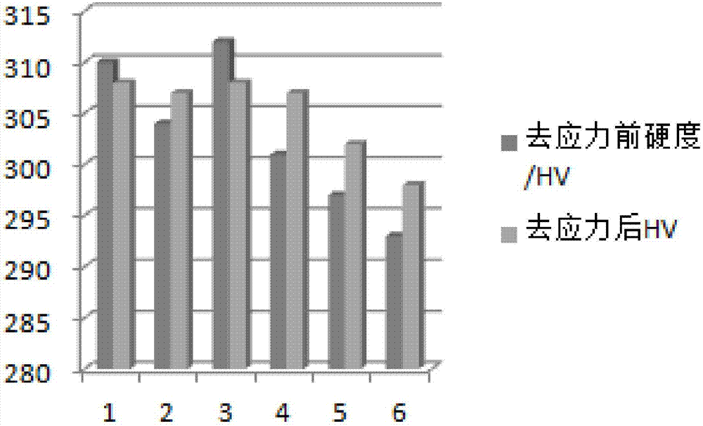
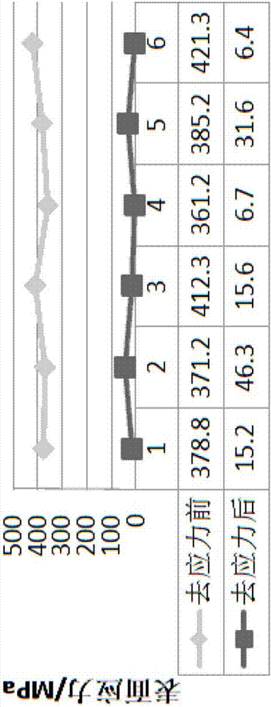
[0020] Specific implementation mode two: combination Figure 1~4 To describe this embodiment, the cage is a tempered 40CrNiMoA semi-finished cage, and the tempering temperature is 590°C to 630°C. With such a design, at this tempering temperature, the cage has excellent serviceability and processing performance, and can implement the subsequent stress relief annealing process at 550±5°C. After quenching and tempering treatment, through the end face, outer circle, inner diameter turning, and drilling and milling processes, there is a large stress on the surface of the cage, and the stress relief annealing is carried out according to the annealing process of the specific implementation mode 1 to fully remove the machining stress on the surface of the cage (see image 3 ), improve the stability of subsequent machining performance, and at the same time maintain the original performance of the guarantee cage (see figure 2 , Figure 4 ). Other compositions and connections are the...
specific Embodiment approach 3
[0021] Specific implementation mode three: combination Figure 1~4 To illustrate this embodiment, the pressure of the nitrogen gas introduced in step 2 is 1-1.5 bar. With this design, the temperature is fully cooled, and the cooling rate is controlled to ensure that the accuracy of the cage is not damaged during stress relief annealing, see Table 1. Other compositions and connections are the same as those in Embodiment 1 or Embodiment 2.
[0022] Specific implementation mode four: combination Figure 1~4 To illustrate this embodiment, in step 2, nitrogen gas is passed through to cool the cage to 43°C or below and then released from the furnace. Other compositions and connections are the same as those in the third embodiment.
[0023] Table 1 Changes in surface accuracy before and after stress relief
[0024]
PUM
 Abstract
Description
Claims
Application Information
 - R&D
- Intellectual Property
- Life Sciences
- Materials
- Tech Scout
- Unparalleled Data Quality
- Higher Quality Content
- 60% Fewer Hallucinations
Browse by: Latest US Patents, China's latest patents, Technical Efficacy Thesaurus, Application Domain, Technology Topic, Popular Technical Reports.
© 2025 PatSnap. All rights reserved.Legal|Privacy policy|Modern Slavery Act Transparency Statement|Sitemap|About US| Contact US: help@patsnap.com