Flue gas heat recycling system

A flue gas heat recovery and flue gas technology, applied in the direction of reducing greenhouse gases, climate sustainability, lighting and heating equipment, etc., can solve the problems of heat waste, landscape pollution, "white smoke" from chimneys, etc., to achieve the solution of white smoke Effects of pollution, increased diffusion rate, broad applicability

Inactive Publication Date: 2017-08-11
保定清科节能技术推广有限公司
View PDF6 Cites 2 Cited by
  • Summary
  • Abstract
  • Description
  • Claims
  • Application Information

AI Technical Summary

Problems solved by technology

[0003] In the process of realizing the present invention, the inventors found at least the following problems: Since the condensation point of the flue gas is generally 55°C or below, the waste heat recovery method using conventional heat exchange is limited by the temperature of the cooling water, and the temperature of the flue gas cannot be lowered. Below the dew point temperature, the heat of condensation cannot be recovered, resulting in serious waste of heat, and an obvious phenomenon of "white smoke" (water vapor condensation) is formed at the chimney, forming landscape pollution; heat pumps are used to generate low-temperature cold water to recover flue gas The waste heat recovery method of heat can reduce the flue gas temperature to 20°C and fully recover the condensation heat of water vapor, but the exhaust smoke is in a saturated state, and the rear flue will produce acidic condensed water, which will corrode the flue. At the same time, Lower exhaust gas temperature is also not conducive to the diffusion and emission of flue gas

Method used


Image

  • Flue gas heat recycling system
  • Flue gas heat recycling system
  • Flue gas heat recycling system

Examples


Embodiment Construction

[0040] In order to make the object, technical solution and advantages of the present invention clearer, the present invention will be further described in detail below in combination with specific embodiments and with reference to the accompanying drawings. It should be understood that these descriptions are exemplary only, and are not intended to limit the scope of the present invention. Also, in the following description, descriptions of well-known structures and techniques are omitted to avoid unnecessarily obscuring the concept of the present invention.

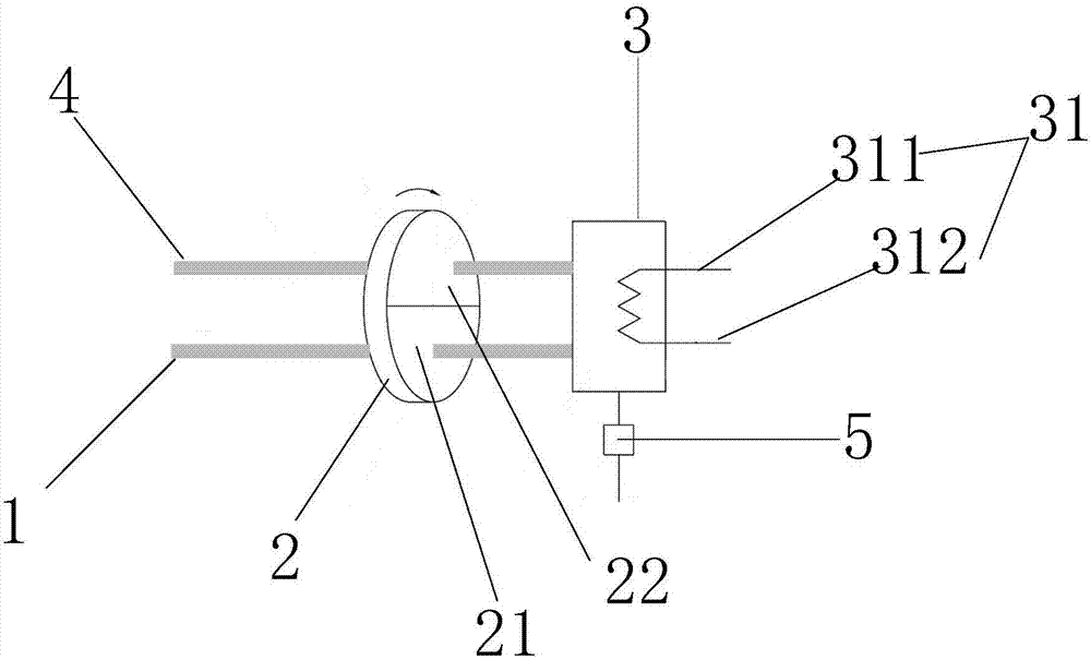
[0041] see figure 1 , figure 1 It is a schematic structural diagram of the flue gas heat recovery system provided by the first embodiment of the present invention.

[0042] Such as figure 1 As shown, the embodiment of the present invention provides a flue gas heat recovery system, which is suitable for the occasions where the temperature of the flue gas discharged from the gas equipment is high and the back pressure is...


PUM


Abstract

The invention discloses a flue gas heat recycling system, and belongs to the technical field of heat recycling. The flue gas heat recycling system comprises a heat exchange wheel (2) which comprises a shell and moisture absorption packing; the shell comprises a regenerating portion (21) and a moisture absorption portion (22), wherein the regenerating portion (21) communicates with a flue gas inlet (1) and is used for bringing away water of the moisture absorption packing through flue gas entering the heat exchange wheel (2), and the moisture absorption portion (22) communicates with a flue gas outlet (4) and is used for absorbing water in the flue gas through the moisture absorption packing and exhausting the flue gas through the flue gas outlet (4); the moisture absorption packing is rotatably arranged in the shell and alternately rotates to the moisture absorption portion (22) and the regenerating portion (21). The flue gas heat recycling system further comprises a condenser (3), one end of the condenser (3) communicates with the regenerating portion (21) to receive the flue gas, and the other end of the condenser (3) communicates with the moisture absorption portion (22) to convey the flue gas and cool the flue gas through cooling water of which the temperature is lower than the dew point temperature of the flue gas entering the condenser (3), so that the water in the flue gas is condensed and drained. According to the flue gas heat recycling system, acidic substances in the flue gas can be removed while flue gas heat is recycled, and the diffusion speed of exhausted flue gas is increased.

Description

technical field [0001] The invention relates to the technical field of waste heat recovery, in particular to a flue gas heat recovery system. Background technique [0002] As a clean energy, natural gas has been more and more widely used. The main component in natural gas is methane (CH4), and in its combustion product (flue gas), water vapor (H 2 The content of O) is about 12-15%, and the heat released by its condensation accounts for about 10% of the combustion calorific value of natural gas, so the potential for energy saving is huge. [0003] In the process of realizing the present invention, the inventors found at least the following problems: Since the condensation point of the flue gas is generally 55°C or below, the waste heat recovery method using conventional heat exchange is limited by the temperature of the cooling water, and the temperature of the flue gas cannot be lowered. Below the dew point temperature, the heat of condensation cannot be recovered, resulti...

Claims


Application Information

Patent Timeline
IPC IPC(8): F23J15/00F23J15/06F23J15/08F23J15/02
CPCF23J15/006F23J15/02F23J15/06F23J15/08Y02E20/30
Inventor 张辉郑赛
Owner 保定清科节能技术推广有限公司
Why Eureka
Try Eureka