Water-saving dust removal and sewage discharge device for chimney

A technology of sewage discharge device and chimney, which is applied in the direction of using liquid separation agent, lighting and heating equipment, and dispersed particle separation, etc., can solve the problems of large smoke and dust in power plants, environmental pollution, etc., and achieve environmental protection, simple and convenient operation and control, and stable operation. Effect

Inactive Publication Date: 2017-08-11
KUNMING UNIV OF SCI & TECH
View PDF4 Cites 0 Cited by
  • Summary
  • Abstract
  • Description
  • Claims
  • Application Information

AI Technical Summary

Problems solved by technology

Due to the large amount of smoke and dust in power plants, even after being treated by dust collectors

Method used


Image

  • Water-saving dust removal and sewage discharge device for chimney

Examples


Example Embodiment

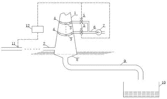
[0019] Embodiment 1: as figure 1 As shown, a water-saving chimney dust removal and sewage discharge device includes a chimney main system composed of a chimney 1 and a smoke inlet pipe 2, a dust removal water pipe 3, an atomizing nozzle 4, a solenoid valve 5, a water inlet pipe 6, a water supply pump 7, and a smoke concentration detection A chimney dust removal system composed of a device 11 and a controller 12, a chimney sewage discharge system composed of a sewage funnel 8, a sewage pipe 9 and a sewage pool 10;

[0020] The smoke inlet pipe 2 in the chimney body system is fixed below the side of the chimney 1; One end of the water inlet pipe 6 is connected to the dust removal pipe 3, and the other end is connected to the treated waste water in the power plant through the water pump 7. Several atomizing nozzles 4 are uniformly installed on the dust removal pipe 3, and the solenoid valve 5 is installed on the water inlet pipe 6. The valve 5 is connected with the controller 12...

Example Embodiment

[0021] Embodiment 2: wherein the dust removal water pipe 3 is fixed on the outer wall of the chimney 1 through a bracket, so as to facilitate the installation and maintenance of the dust removal water pipe 3, a through hole is drilled on the outer wall of the chimney 1, and the atomizing nozzle 4 is fixed on the dust removal water pipe 3 and runs through the chimney The through hole on 1 extends into the chimney 1, wherein the atomizing nozzle 4 is resistant to high temperature and corrosion and is threadedly connected with the dust removal water pipe 3, and the dust removal water pipe 3 and the water inlet pipe 6 are also threaded. Repair and maintenance of components.

Example Embodiment

[0022] Embodiment 3: The dust removal water pipes 3 are installed in two to four rows, and evenly installed at 5-8m above the smoke inlet pipe, which is beneficial to improve the dust removal efficiency.


PUM

PropertyMeasurementUnit
Diameteraaaaaaaaaa
Diameteraaaaaaaaaa

Abstract

The invention relates to a water-saving dust removal and sewage discharge device for a chimney, and belongs to the technical field of dust removal and sewage discharge. The device comprises the chimney, a smoke inlet pipeline, dust removal water pipes, atomization spray nozzles, a stop valve, a water inlet pipe, a water feed pump, a sewage discharge hopper, a sewage discharge pipe and a sewage discharge pool. The smoke inlet pipeline is fixed to the lower portion of one side of the chimney. The dust removal water pipes are fixed to the outer wall of the chimney and located above the smoke inlet pipeline. One end of the water inlet pipe is connected with the dust removal water pipes, and the other end of the water inlet pipe is connected with waste water, processed in a power plant, through a water pump. The multiple atomization spray nozzles are evenly installed on the dust removal water pipes. Electromagnetic valves are installed on the water inlet pipe and are connected with a controller. The controller is connected with a smoke concentration detector. The smoke concentration detector is installed at a boiler smoke discharge outlet. The sewage discharge hopper is located at the bottom of the chimney. The sewage discharge hopper communicates with the sewage discharge pool through the sewage discharge pipe. Dust removal is conducted on the chimney through water in a reclaimed water station, water resources are saved, meanwhile, environment protection is achieved, operation is easy and convenient, and operation is stable.

Description

technical field [0001] The invention relates to a water-saving chimney dust removal and sewage discharge device, which belongs to the technical field of dust removal and sewage discharge. Background technique [0002] Atmospheric environmental issues that countries around the world are concerned about today include acid rain, ozone layer destruction, and the greenhouse effect. Acid rain refers to various forms of atmospheric precipitation such as rain, snow, fog, frost, dew, hail, and graupel with a pH value less than 5.6, which is a manifestation of atmospheric pollution. According to reports, in 1980, nearly 30 million tons of sulfuric acid fell on the earth through rainwater. Sulfuric acid and nitric acid are converted from anthropogenic emissions of sulfur dioxide and nitrogen oxides. The main substance that forms acid rain is SO2. Acid rain is extremely harmful. If the acidity of precipitation is lower than pH 5, the ecological balance will be destroyed. For example,...

Claims


Application Information

Patent Timeline
IPC IPC(8): F23J15/04B01D47/06
CPCF23J15/04B01D47/06F23J2217/50
Inventor 罗小林刘启航
Owner KUNMING UNIV OF SCI & TECH
Why Eureka
Try Eureka