Comprehensive utilization system of waste heat of ring cooling machine low-temperature exhaust gas and sintering large flue smoke

A flue gas waste heat and ring cooler technology is applied in the field of comprehensive utilization system of sintering waste heat, which can solve the problem of not doing waste heat recovery, and achieve the effect of reducing operating costs and increasing waste heat recovery.

Pending Publication Date: 2017-08-18
HUATIAN NANJING ENG & TECH CORP MCC
View PDF4 Cites 0 Cited by
  • Summary
  • Abstract
  • Description
  • Claims
  • Application Information

AI Technical Summary

Problems solved by technology

At present, most domestic sintering plants recover waste heat from sintering mainly in high-temperature waste gas waste heat recovery ...

Method used


Image

  • Comprehensive utilization system of waste heat of ring cooling machine low-temperature exhaust gas and sintering large flue smoke

Examples


Embodiment 1

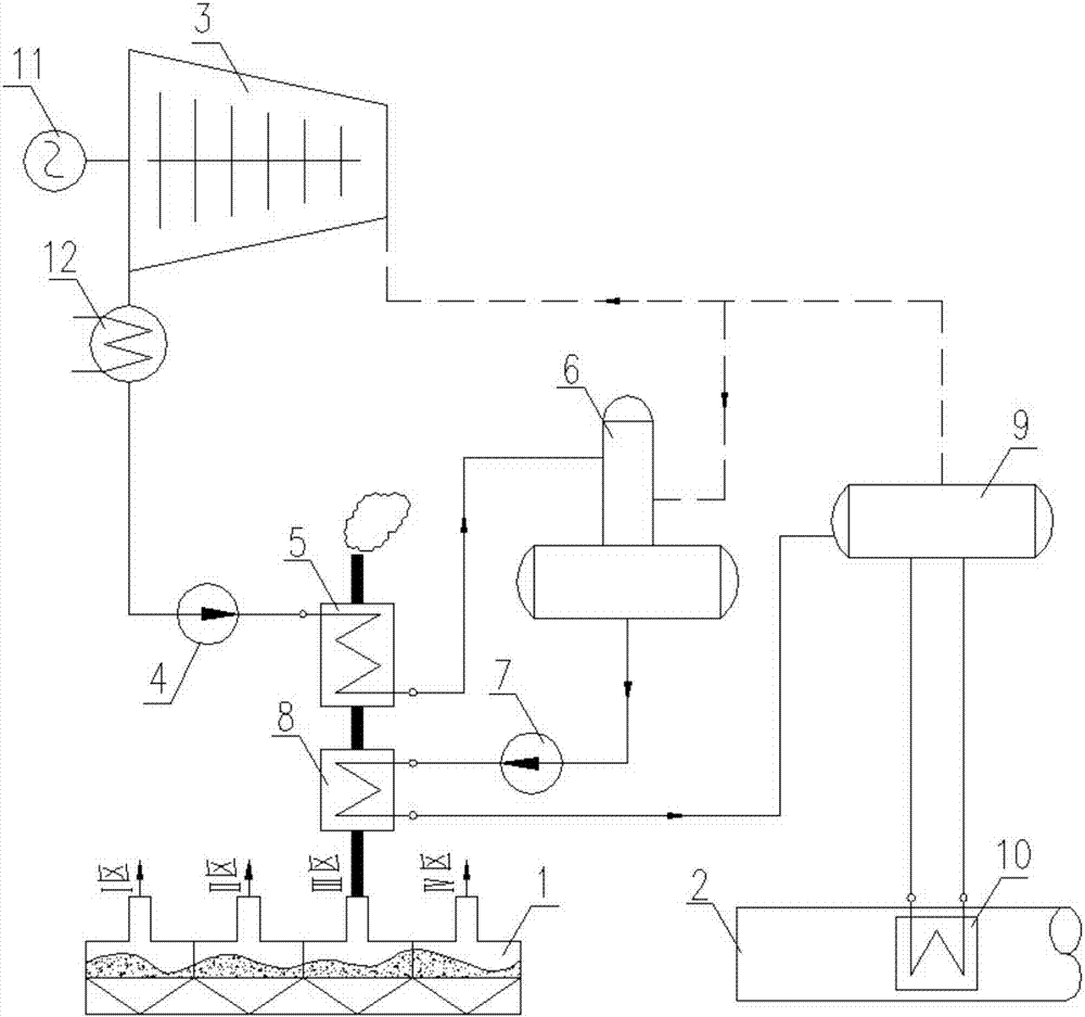
[0024] Such as figure 1 As shown, in this embodiment, the condensed water condensed in the condenser 13 is pumped into the feedwater preheater 5 through the condensate pump 4 to absorb the waste heat of the exhaust gas that has been heat exchanged by the economizer 8, and the temperature rises to the next Enters the deaerator and the water tank 6, the water after deaeration enters the feed water pump 7 to pressurize and then enters the economizer 8, absorbs the low temperature (100~150℃) waste heat of the ring cooler III zone and enters the steam drum In 9, the steam drum 9 and the evaporator 10 are connected to each other through at least two pipelines. The water absorbs the heat of the exhaust gas in the evaporator 10 and then transforms into a steam-water mixture and enters the steam drum 9. This part of the hydraulic cycle relies on the inlet and outlet of the evaporator 10. The weight difference of the medium in the end pipeline is completed, forming a natural circulation ...

Embodiment 2

[0028] On the basis of embodiment 1, the water inlet of the waste heat recovery device in the low temperature zone of the annular cooler is in communication with a water supply pipeline, and the water supply pipeline is provided with a water supply regulating valve group;

[0029] A liquid level sensor is provided in the steam-water separation device, and the feedwater regulating valve group is used to receive a signal sent by the liquid level sensor to control the water level of the steam-water separation device within a preset range.


PUM


Abstract

The invention discloses a comprehensive utilization system of waste heat of ring cooling machine low-temperature exhaust gas and sintering large flue smoke. The comprehensive utilization system of the waste heat of the ring cooling machine low-temperature exhaust gas and the sintering large flue smoke comprises a steam pocket, a ring cooling machine low-temperature area waste heat recycling device, a sintering large flue waste heat recycling device and a steam power generation device. A water outlet of the ring cooling machine low-temperature area waste heat recycling device communicates with a water inlet of the steam pocket. A water outlet of the steam pocket communicates with a water inlet of the sintering large flue waste heat recycling device. A steam water outlet of the sintering large flue waste heat recycling device communicates with a steam water inlet of the steam pocket. A steam outlet of the steam pocket communicates with a steam inlet of the steam power generation device. A water outlet of the steam power generation device communicates with a water inlet of the ring cooling machine low-temperature area waste heat recycling device. The comprehensive utilization system of the waste heat of the ring cooling machine low-temperature exhaust gas and the sintering large flue smoke recycles the waste heat of sintering high-temperature smoke of a sintering machine and waste heat of low-temperature exhaust gas at the temperature of 100-150 DEG C of a III area of a ring cooling machine, a heating surface is reasonably arranged according to the second law of thermodynamics, stairstep recycling of the waste heat of the smoke is achieved, and the recycling amount of the waste heat is improved to the greatest extent.

Description

Technical field [0001] The invention relates to a comprehensive utilization system of sintering waste heat. Background technique [0002] The waste heat resources of the sintering production process mainly include two parts: the waste heat of the high-temperature waste flue gas from the sintering machine and the waste heat of the sinter cooling waste gas on the ring cooler. In the total energy consumption of the sintering process, the waste heat of the two parts of the waste gas is close to 50% Heat. At present, most domestic sintering plants recover sintering waste heat mainly in the high temperature waste heat recovery of zone I and II on the ring cooler. The low temperature waste gas of zone III is generally directly discharged without waste heat recovery. Summary of the invention [0003] In view of the above-mentioned problems, the present invention provides a system for comprehensive utilization of low-temperature exhaust gas of an annular cooler and waste heat of sintering...

Claims


Application Information

Patent Timeline
IPC IPC(8): F01K27/02F22B1/18F27D17/00
CPCF01K27/02F22B1/18F27D17/004F27D2017/006Y02P10/25
Inventor 王雷
Owner HUATIAN NANJING ENG & TECH CORP MCC
Why Eureka
Try Eureka