Concentrated winding DC bias-type hybrid excitation permanent magnet motor

A technology of concentrated winding and mixed excitation, applied in the shape/style/structure of winding conductors, synchronous machines, electromechanical devices, etc., can solve the problems of low-speed operation efficiency and low power factor, high rotor loss of asynchronous motors, limited magnetic field adjustment capabilities, etc. problem, to achieve the effect of large output torque, high reliability of high-speed operation, and strong magnetic field adjustment ability

Active Publication Date: 2017-08-18
HUAZHONG UNIV OF SCI & TECH
View PDF4 Cites 13 Cited by
  • Summary
  • Abstract
  • Description
  • Claims
  • Application Information

AI Technical Summary

Problems solved by technology

Brushed DC motors, asynchronous motors and reluctance motors are due to their inherent structural defects: brushes and mechanical commutators are required for brushed DC motors; asynchronous motors have high rotor losses, low-speed operating efficiency and low power factor; magnetic The problem of high torque ripple of resistive motors, and the application in the field of traction motors is limited
[0008] (1) The motor needs a special excitation winding. Although the excitation coil is a concentrated winding, its end is still very long, the copper material consumption is large, and the motor structure is complicated;
[0009] (2) The magnetic circuit of the excitation magnetic potential generated by the excitation coil must pass through the permanent magnet. Structurally speaking, it belongs to a series hybrid excitation structure. Since the permanent magnet has a low permeability and a large reluctance, it requires a large The excitation current can adjust the air gap magnetic density, the excitation copper consumption is large, and the magnetic field adjustment ability is limited
[0010] (3) When the excitation magnetic potential passes through the permanent magnet, if the direction of the excitation magnetic potential is opposite to the magnetization direction of the permanent magnet, there may be a risk of demagnetization of the permanent magnet

Method used


Image

  • Concentrated winding DC bias-type hybrid excitation permanent magnet motor
  • Concentrated winding DC bias-type hybrid excitation permanent magnet motor
  • Concentrated winding DC bias-type hybrid excitation permanent magnet motor

Examples


Embodiment Construction

[0056] In order to make the object, technical solution and advantages of the present invention clearer, the present invention will be further described in detail below in conjunction with the accompanying drawings and embodiments. It should be understood that the specific embodiments described here are only used to explain the present invention, not to limit the present invention. In addition, the technical features involved in the various embodiments of the present invention described below can be combined with each other as long as they do not constitute a conflict with each other.

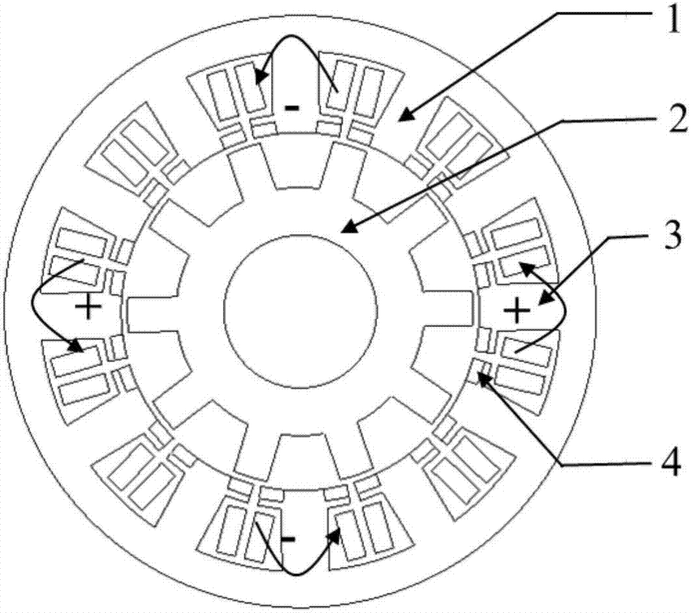
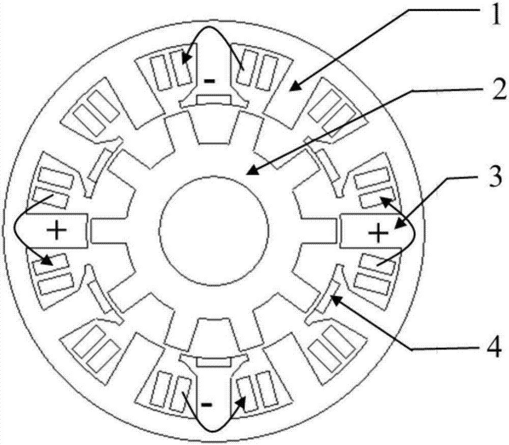
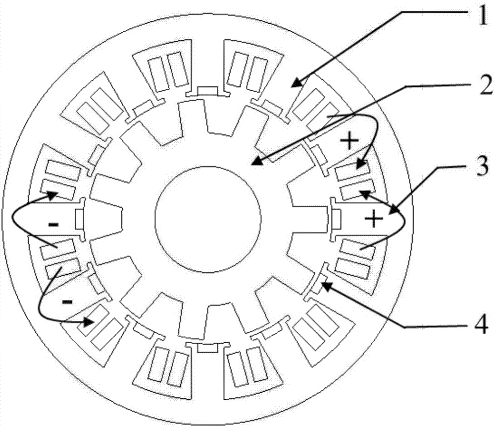
[0057] figure 1 It is a concentrated winding DC bias type hybrid excitation permanent magnet motor topology according to an embodiment of the present invention. The stator has 12 slots, the rotor has 10 slots, the windings have 5 pairs of poles, the number of permanent magnet pole pairs is 6, and the DC excitation pole pairs The number is 6. Such as figure 1 As shown, the hybrid excitation pe...


PUM


Abstract

The invention discloses a concentrated winding DC bias-type hybrid excitation permanent magnet motor, which comprises a stator (1), a rotor (2), a winding (3) and permanent magnets (4), wherein the rotor has a slotted convex pole structure. The concentrated winding DC bias-type hybrid excitation permanent magnet motor is characterized in that the stator (1) has a toothed boot structure, slots are arranged at two sides of the top ends of stator teeth or in the middle of top ends of an uneven number of stator teeth for accommodating the permanent magnets (4); and the winding (3) adopts a fractional-slot non-overlapped concentrated winding, and current in the winding comprises an AC component and a DC component. According to the hybrid excitation permanent magnet motor of the invention, as a special excitation winding is omitted, in a condition with the same copper consumption, the output torque is larger; reluctance in an excitation magnetic field generated by the DC component in an armature winding is little, and the magnetic field adjustment ability is strong; in short circuit fault, the short circuit current is small and the reliability is high; and besides, the motor structure is greatly simplified, the processing process is simple, and the cost is reduced.

Description

technical field [0001] The invention belongs to the field of hybrid excitation permanent magnet motors, and more specifically relates to a concentrated winding DC bias type hybrid excitation permanent magnet motor. Background technique [0002] Under the dual pressure of energy saving, emission reduction and environmental protection, hybrid and pure electric vehicle technologies with high energy efficiency, low noise, and environmental protection have attracted more and more attention from governments and industries. my country has already listed new energy vehicles as one of the seven strategic emerging industries in the national "Twelfth Five-Year Plan". At present, almost all automobile companies have launched their own hybrid vehicles or pure electric vehicles. [0003] As the main source of power for hybrid or pure electric vehicles, traction motors are required to have a wide range of constant power speed regulation in addition to high efficiency, high reliability, an...

Claims


Application Information

Patent Timeline
Patent Type & Authority Applications(China)
IPC IPC(8): H02K21/04H02K3/12
CPCH02K3/12H02K21/042
Inventor 曲荣海贾少锋李健李大伟孔武斌
Owner HUAZHONG UNIV OF SCI & TECH
Why Eureka
Try Eureka