
Surface protection film and optical part bonded with the surface protection film

A surface protection film, peeling film technology, applied in the direction of optical elements, optics, film/sheet adhesives, etc., can solve the problem of difficult to stick FPR film and so on

Active Publication Date: 2021-06-15
FUJIMORI KOGYO CO LTD
View PDF13 Cites 0 Cited by
  • Summary
  • Abstract
  • Description
  • Claims
  • Application Information

AI Technical Summary

Problems solved by technology

However, if the surface of an optical film such as a polarizer is contaminated with an adhesive or an antistatic agent used in a surface protection film, there is a problem that it is difficult to attach the FPR film

Method used

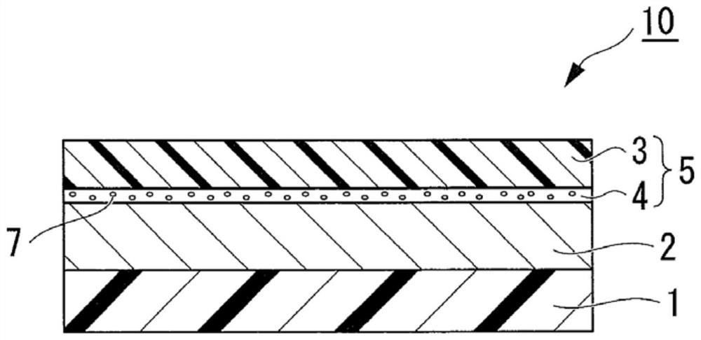

Image

  • Surface protection film and optical part bonded with the surface protection film
  • Surface protection film and optical part bonded with the surface protection film
  • Surface protection film and optical part bonded with the surface protection film

Examples


Embodiment 1

[0080] (Preparation of surface protection film)

[0081] 5 parts by weight of addition reaction silicone (manufactured by Dow Corning Toray Co., Ltd., trade name: SRX-345), 0.75 parts by weight of N-butyl-4 as an ionic compound with a melting point of 48° C. -picoline hexafluorophosphate, 0.75 parts by weight of tetraethylene glycol di-2-ethylhexanoate, 95 parts by weight of toluene and ethyl acetate as a 1:1 mixed solvent, 0.05 parts by weight of platinum catalyst (manufactured by Dow Corning Toray Co., Ltd., trade name: SRX-212) were mixed, stirred and mixed, and the coating material for forming the release agent layer of Example 1 was prepared. On the surface of a polyethylene terephthalate film with a thickness of 38 μm, the paint used to form the release agent layer of Example 1 was coated with a Meyer bar so that the thickness after drying was 0.2 μm, and a 120° C. Dry in a hot air circulation oven for 1 minute to obtain the peeling film of Example 1. On the other hand...

Embodiment 2

[0084] In the same manner as in Example 1, except that instead of N-butyl-4-methylpyridine hexafluorophosphate, 1-methyl-3-ethylimidazolium hexafluorophosphate, which is an ionic compound having a melting point of 62°C, was used Thus, the surface protective film of Example 2 was obtained.

Embodiment 3

[0093]Except for using the following adhesive composition instead of the adhesive composition of Example 1, the surface protection film of Example 3 was obtained in the same manner as in Example 1. In this adhesive composition, relative to 100 parts by weight of 30% ethyl acetate solution of the adhesive polymer formed by the copolymer of 58 parts by weight of 2-ethylhexyl acrylate, 38 parts by weight of butyl acrylate, and 4 parts by weight of 2-hydroxyethyl acrylate, adding In addition, 1.2 parts by weight of an isocyanate curing agent (manufactured by TOSOH CORPORATION, trade name: Coronate (registered trademark) HX) was mixed.


PUM

PropertyMeasurementUnit
melting pointaaaaaaaaaa
peel strengthaaaaaaaaaa

Abstract

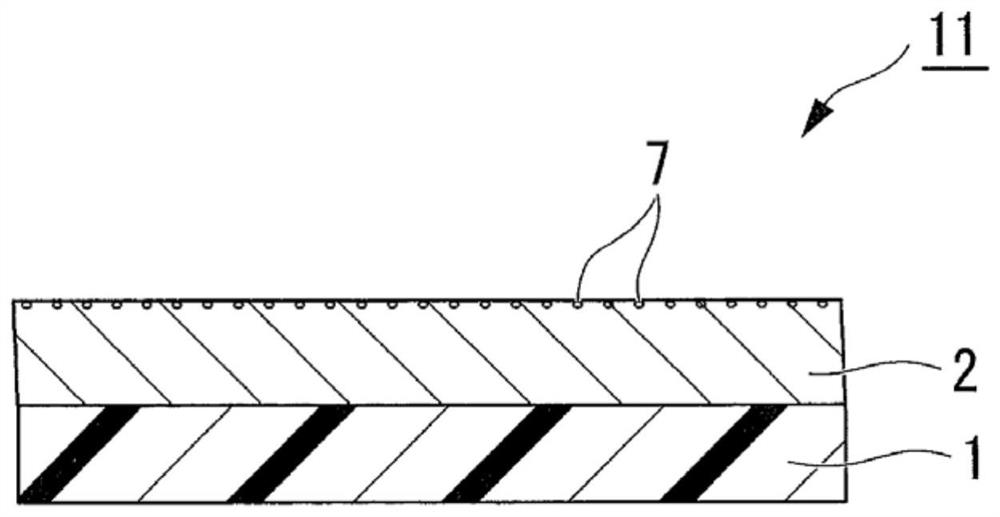
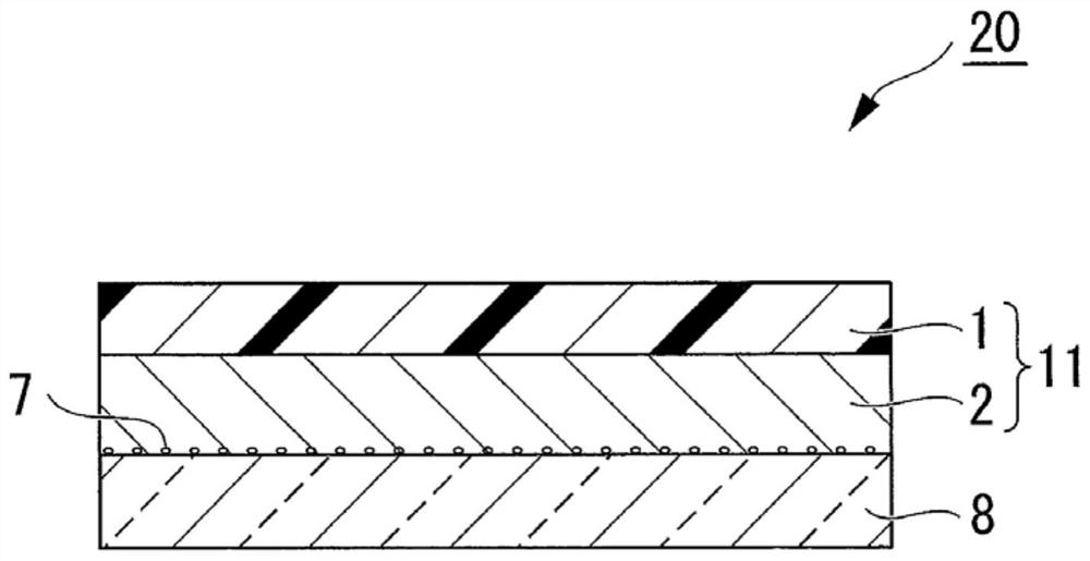
The present invention provides an optical film having irregularities on the surface which can also be used, has less contamination to adherends, has low contamination to adherends that does not change over time, and has excellent anti-peeling static electricity that does not deteriorate over time Performance surface protection film and optical components using the same. A surface protective film (10) is formed by laminating a release film (5) having a release agent layer (4) on an adhesive layer (2), and the release film (5) is formed by laminating one side of a resin film (3) A release agent layer (4) comprising a release agent mainly composed of polydimethylsiloxane, an antistatic agent that does not react with the release agent, and an ester containing at least one ether bond plasticizer, the antistatic agent component is an ionic compound with a melting point of 30 to 80°C, and the antistatic agent component and the ester plasticizer are transferred from the release agent layer (4) of the release film (5) to the adhesive layer ( 2) On the surface, the peeling electrostatic voltage when peeling the adhesive layer (2) from the adherend is reduced.

Description

technical field [0001] The present invention relates to a surface protection film bonded to the surface of optical components (hereinafter, sometimes referred to as an optical film) such as a polarizing plate, a retardation plate, and a lens film for a display. More specifically, to provide a surface protection film with less contamination to an adherend, and further, to provide a surface protection film having excellent anti-peeling electrostatic performance that does not deteriorate with time, and a product using the surface protection film optics. Background technique [0002] Conventionally, optical films such as polarizing plates, retardation plates, lens films for displays, anti-reflection films, hard coat films, transparent conductive films for touch panels, and displays using these films have been used. When producing products, a surface protection film is attached to the surface of the optical film to prevent dirt or scratches on the surface in subsequent processes...

Claims


Application Information

Patent Timeline
Patent Type & Authority Patents(China)
IPC IPC(8): C09J7/25C09J7/30C09J133/08
CPCC08K5/06C08K5/3432C09D5/24C09D183/04C09J133/08C09J2203/318C09J2433/00C09J2467/005C09J2467/006C09D7/63C09J7/401G02B5/30C08K5/10C08K2201/017C09J7/20C09J7/385G02B1/11G02B1/14G02B1/16
Inventor 小林弘幸春日充新见洋人铃木千惠五十岚智美木俣绘美子林益史
Owner FUJIMORI KOGYO CO LTD
Learn More