Laser scanning saturate structured light illumination microscopic method and device based on phase modulation

A technology of structured light illumination and laser scanning, applied in the field of confocal microscopy, can solve problems such as photobleaching and damage to fixed samples, and achieve the effects of easy operation, reduced requirements, and reduced light intensity

Inactive Publication Date: 2017-08-25
ZHEJIANG UNIV
View PDF6 Cites 14 Cited by
  • Summary
  • Abstract
  • Description
  • Claims
  • Application Information

AI Technical Summary

Problems solved by technology

However, due to the extremely high optical power requirements for nonlinear responses, saturated structured light illumination is very prone to photobleachin...

Method used


Image

  • Laser scanning saturate structured light illumination microscopic method and device based on phase modulation
  • Laser scanning saturate structured light illumination microscopic method and device based on phase modulation
  • Laser scanning saturate structured light illumination microscopic method and device based on phase modulation

Examples


Embodiment 1

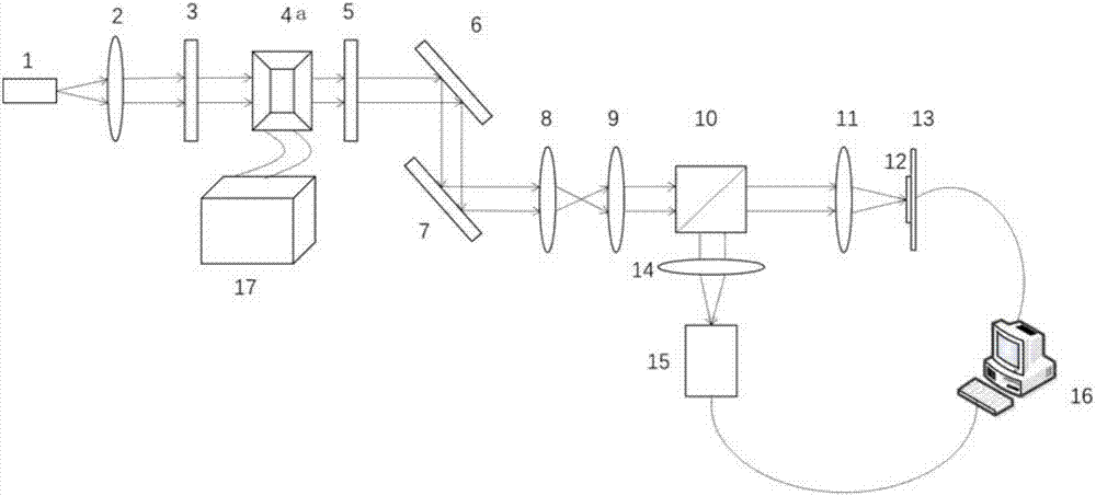
[0058] Such as figure 1 As shown, it is a phase-modulated laser scanning saturation structured illumination microdevice modulated by a spatial light modulator, including a laser 1, a collimator lens 2, a polarizer 3, a spatial light modulator 4a, and a half-wave plate 5. Scanning galvanometer 6 in x direction, 7 galvanometer scanning in y direction, scanning lens 8, field lens 9, dichromatic mirror 10, objective lens 11, sample 12, stage 13, lens 14, photodetector 15, computer 16 and spatial light modulator control box 17.

[0059] use figure 1 The shown device implements phase modulation-based laser scanning saturated structured illumination microscopy for fluorescent samples, and the process is as follows:

[0060] (1) Laser 1 emits illumination light, which is collimated by collimating lens 2;

[0061] (2) The collimated illumination light is polarized into linearly polarized light by the polarizer 3;

[0062] (3) The polarized illumination light passes through the sp...

Embodiment 2

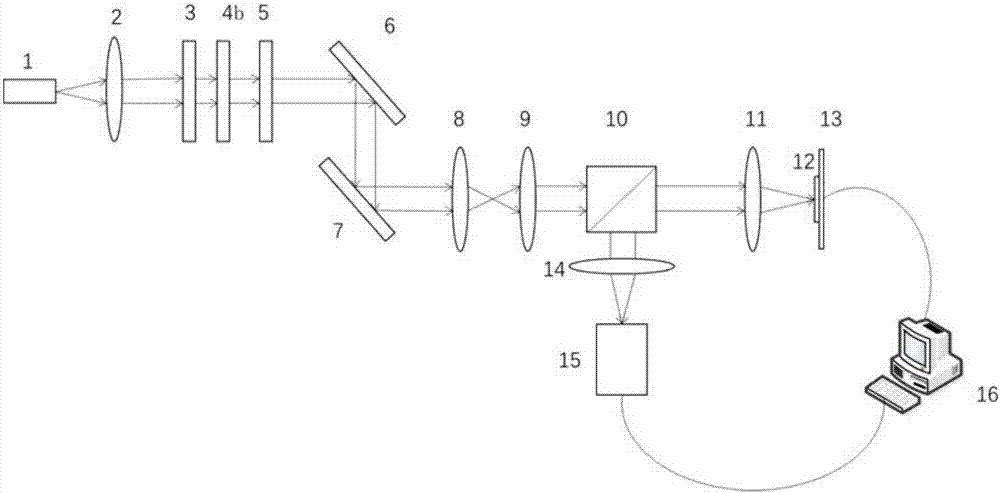
[0066] Such as image 3 As shown, it is a phase-modulated laser scanning saturation structured illumination microdevice modulated by a 0-π phase plate, including a laser 1, a collimator lens 2, a polarizer 3, and a 0-π phase plate 4b, Half-wave plate 5, scanning vibrating mirror 6 in x direction, scanning vibrating mirror 7 in y direction, scanning lens 8, field mirror 9, dichromatic mirror 10, objective lens 11, sample 12, stage 13, lens 14, photodetector 15 and computer 16 .

[0067] use image 3 The shown device implements phase modulation-based laser scanning saturated structured illumination microscopy for fluorescent samples, and the process is as follows:

[0068] (1) Laser 1 emits illumination light, which is collimated by collimating lens 2;

[0069] (2) The collimated illumination light is polarized into linearly polarized light by the polarizer 3;

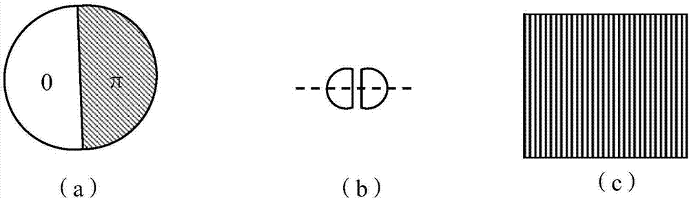
[0070] (3) The polarized illumination light passes through the 0-π phase plate 4b to load the 0-π phase, then pass...


PUM


Abstract

The invention discloses a laser scanning saturate structured light illumination microscopic method based on phase modulation, and the method comprises the steps: enabling an illumination light beam after collimation to be converted into linear polarized light; loading a phase (0-phi) in a first direction to the linear polarized light, and adjusting the polarization direction of the linear polarized light; scanning a sample through the linear polarized light after the adjustment of the polarization direction, forming a first laser scanning saturate structured light illumination pattern where the sample is excited to generate fluorescent light, and collecting a first fluorescent light signal; loading a phase (0-phi) in a second direction to the linear polarized light, and adjusting the polarization direction of the linear polarized light; scanning a sample through the linear polarized light after the adjustment of the polarization direction, forming a second laser scanning saturate structured light illumination pattern where the sample is excited to generate fluorescent light, and collecting a second fluorescent light signal; carrying out the processing of the first and second fluorescent light signals, and obtaining a super-resolution image with the improved lateral resolution. The invention also discloses a laser scanning saturate structured light illumination microscopic device based on phase modulation.

Description

technical field [0001] The invention belongs to the field of confocal microscopy, and in particular relates to a phase modulation-based laser scanning saturation structured light illumination microscopy method and device. Background technique [0002] The confocal microscope uses the laser beam to form a point light source through the optical system to scan the sample at the focal plane of the objective lens. Illuminated points on the focal plane are imaged at the detection pinhole, while points outside the focal plane are not imaged at the detection pinhole. The image information of the irradiated point is received point by point by the photodetector after detecting the pinhole, and the fluorescent image is quickly formed on the computer monitor screen. The confocal image obtained in this way is the optical cross-section of the focal plane of the objective lens in the sample. However, according to the diffraction theory, the resolving power of the microscope is related to ...

Claims


Application Information

Patent Timeline
IPC IPC(8): G02B21/00G01N21/64
CPCG02B21/0048G01N21/6458G01N2021/6463G01N2201/061G01N2201/1053G02B21/0032G02B21/0068G02B21/0076G02B21/0092
Inventor 刘旭孙试翼匡翠方黄玉佳
Owner ZHEJIANG UNIV
Why Eureka
Try Eureka