Environment-friendly waste cutting fluid circulation treatment method and purification device

A technology of waste cutting fluid and recycling treatment, applied in filtration treatment, multi-stage water treatment, chemical instruments and methods, etc., can solve the problems of increasing the use of waste cutting fluid, reducing the lubricity of cutting fluid, and difficult to control oil quality. , to reduce the economic burden, improve the sterilization rate, and achieve good environmental protection effects.

Inactive Publication Date: 2017-08-29
苏州易歌环境科技有限公司
View PDF5 Cites 10 Cited by
  • Summary
  • Abstract
  • Description
  • Claims
  • Application Information

AI Technical Summary

Problems solved by technology

However, due to the unevenness of cutting oil products on the market, it is difficult to control the oil quality of cutting fluid in the cutting process; it also increases the use of waste cutting fluid in environmental protection.
[0003] Generally speaking, in the process of cutting, there are two criteria for judging the replacement cycle of water-based cutting fluid; one is that the lubrication of the cutting fluid itself is reduced and cannot achieve the original effect; the other is the peculiar smell caused by the deterioration of the cutting fluid; the cutting fluid itself The reduction of lubricity can be increased by quantitative replenishment; but the peculiar smell caused by the deterioration of the cutting fluid will be unbearable, especially the volatilization of formaldehyde added in it for a long time will cause the operator to vomit, dizzy, etc. uncomfortable phenomenon

Method used


Image

  • Environment-friendly waste cutting fluid circulation treatment method and purification device
  • Environment-friendly waste cutting fluid circulation treatment method and purification device
  • Environment-friendly waste cutting fluid circulation treatment method and purification device

Examples


Embodiment Construction

[0032] The present invention will be further described below in conjunction with specific embodiments.

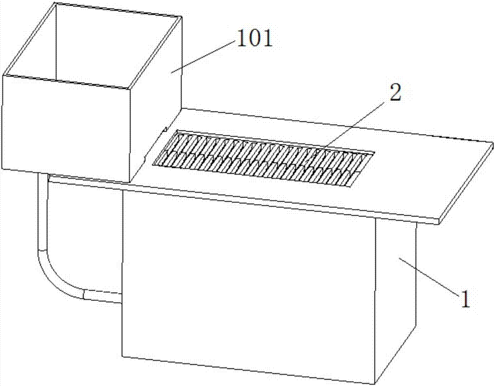
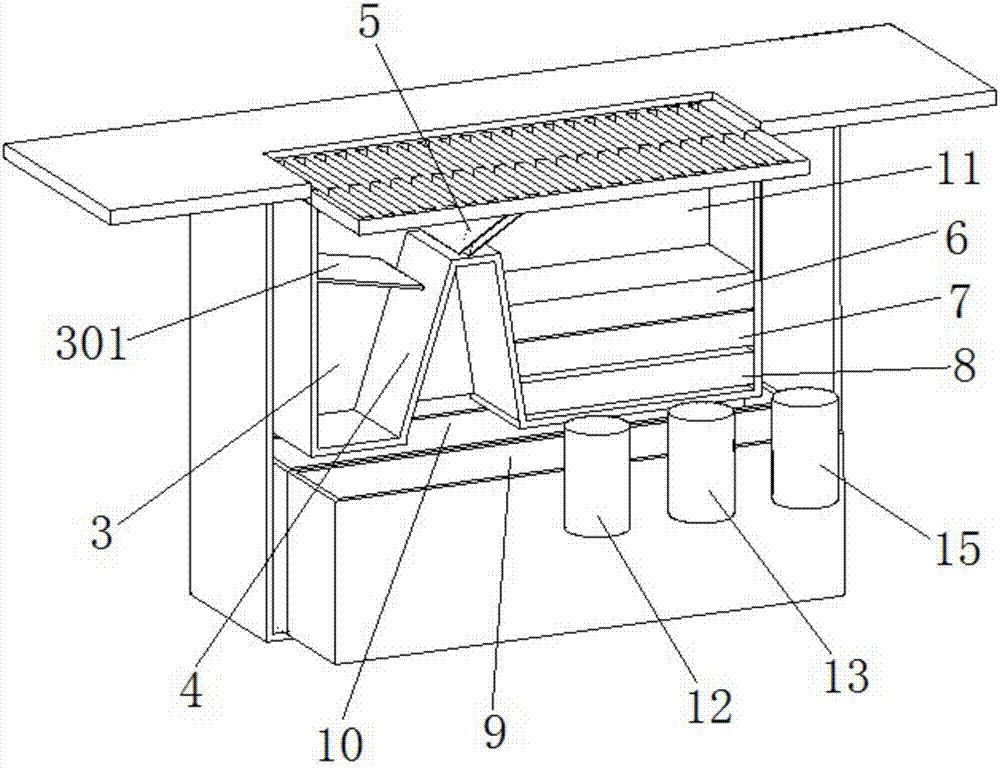
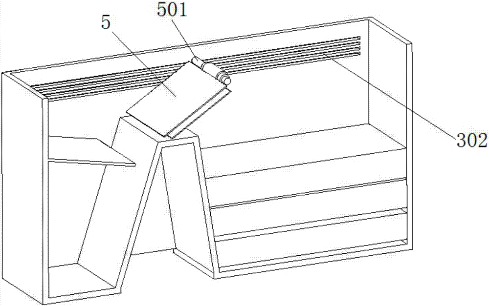
[0033] Such as Figure 1 to Figure 5 as shown,

[0034] An environment-friendly recycling and purification equipment for waste cutting fluid, comprising a body 1, a cutting fluid circulation tank 101 and a liquid inlet 2 arranged on the top of the body 1, an oil-water separation tank, a waste cutting fluid working tank 10 and a cutting fluid The temporary storage tank 9, the cutting fluid circulation tank 101, the oil-water separation tank, the waste cutting fluid working tank 10 and the cutting fluid temporary storage tank 9 are connected in sequence, the oil-water separation tank is located below the liquid inlet 2, and the waste cutting fluid in the cutting fluid circulation tank 101 The liquid first enters the oil-water separation tank, and is then transported by pumping equipment (such as a pump) to the waste cutting fluid working tank 10 and the cutting fluid tempora...


PUM

PropertyMeasurementUnit
pore sizeaaaaaaaaaa
pore sizeaaaaaaaaaa
pore sizeaaaaaaaaaa

Abstract

The invention discloses an environment-friendly waste cutting fluid circulation treatment method and a purification device and belongs to the technical field of a cutting fluid. The method comprises heating a waste cutting fluid sent from a cutting fluid circulation tank to 30 to 42 DEG C, carrying out coarse filtration, then feeding the filtrate into an oil-water separation tank, carrying out primary oil-water separation through an oil scraper assembly, feeding heavy oil from an overflow port of the oil-water separation tank to an oil-water separator, carrying out secondary oil-water separation to obtain a 1-level clear liquid, filtering to remove impurities in the 1-level clear liquid through filter films having different network densities to obtain a 2-level clear liquid, conveying the 2-level clear liquid into a waste cutting liquid work tank, adjusting pH of the 2-level clear liquid to greater than or equal to 9, adding an antibacterial agent into the 2-level clear liquid to obtain a 3-level clear liquid, conveying the 3-level clear liquid into the cutting fluid circulation tank and carrying out recycling. The method has the advantages of simple processes, low energy consumption and high water recovery rate. The separated cutting liquid can be used for preparation of a cutting liquid or be conveyed into a sewage treatment system, subjected to biochemical treatment and discharged.

Description

technical field [0001] The invention belongs to the technical field of cutting fluid, and more specifically relates to an environment-friendly waste cutting fluid circulation treatment method and purification equipment thereof. Background technique [0002] Cutting fluid is an indispensable product in the machining production of the hardware manufacturing industry. It has the functions of cutting lubrication and lowering the temperature to protect the cutting tool and ensure the accuracy of the processed parts. However, due to the unevenness of cutting oil products on the market, it is difficult to control the oil quality of cutting fluid in the cutting process; it also increases the use of waste cutting fluid in environmental protection. [0003] Generally speaking, in the process of cutting, there are two criteria for judging the replacement cycle of water-based cutting fluid; one is that the lubrication of the cutting fluid itself is reduced and cannot achieve the origina...

Claims


Application Information

Patent Timeline
Patent Type & Authority Applications(China)
IPC IPC(8): C02F9/04
CPCC02F9/00C02F1/66C02F1/50C02F1/40C02F1/001C02F2301/08
Inventor 刘祥虎安继红
Owner 苏州易歌环境科技有限公司
Why Eureka
Try Eureka