
Compound sintered compact cutting tool and compound sintered compact cutting tool with coated surface

A technology of cutting tools and sintered bodies, which is applied in the direction of manufacturing tools, workpieces, drilling accessories, etc., can solve problems such as chipping, insufficient strength, toughness, and insufficient heat cracking resistance, and achieve the effect of suppressing deformation

Active Publication Date: 2017-08-29
MITSUBISHI MATERIALS CORP
View PDF8 Cites 10 Cited by
  • Summary
  • Abstract
  • Description
  • Claims
  • Application Information

AI Technical Summary

Problems solved by technology

[0010] In the composite sintered cutting tools as shown in the above-mentioned patent documents 1 and 2, although the amount of tungsten used can be reduced to some extent, 15% by mass or more of W and WC are required in the cermet, so that the use of tungsten The amount of reduction is not sufficient, and when this cutting tool is used for wet interrupted cutting, not only the strength and toughness are not sufficient, but also the heat cracking resistance is not sufficient, so abnormal damage such as chipping and chipping is likely to occur The problem
[0011] Furthermore, in the composite sintered body composed of cemented carbide and cermet shown in Patent Document 3, it is necessary not only to form irregularities at the boundary between the cemented carbide layer and the cermet layer, but also to obtain a sintered body with less deformation during sintering. Composite sintered body needs to make the shrinkage characteristics of sintered stamped body consistent between dissimilar materials. Therefore, in cutting tools made of this composite sintered body, the reduction of tungsten usage can only stay at about 30%. Not only is it not fully satisfactory from the point of view of saving resources, but also it cannot be said that it has sufficient reliability because it may damage the cemented carbide of the insert due to the expansion of cracks under cutting conditions such as wet interrupted cutting and other strong thermal processes.

Method used


Image

  • Compound sintered compact cutting tool and compound sintered compact cutting tool with coated surface
  • Compound sintered compact cutting tool and compound sintered compact cutting tool with coated surface
  • Compound sintered compact cutting tool and compound sintered compact cutting tool with coated surface

Examples


Embodiment 1

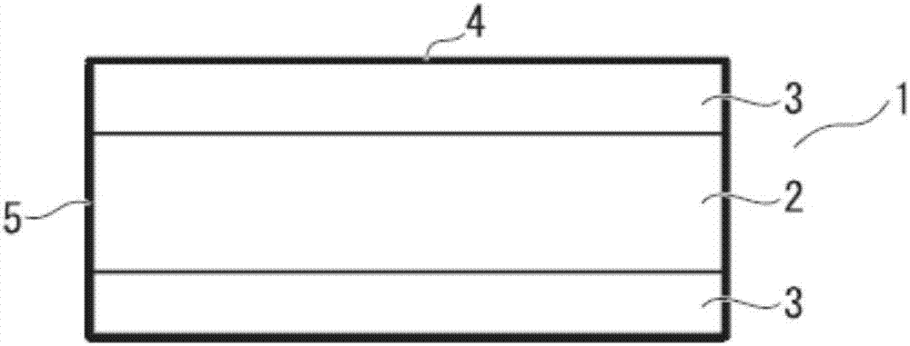
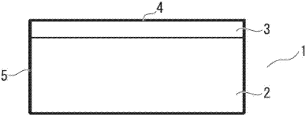
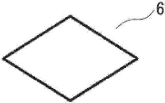
[0089] In Example 1, a tool having a rake face made of WC-based cemented carbide having a polygonal planar shape formed on only one side of the TiCN-based cermet will be described.

[0090] First, WC-based cemented carbide raw material powders having a compounding composition shown in Table 1 and an average particle diameter of 0.5 to 3 μm were prepared.

[0091] Then, TiCN-based cermet raw material powder having a compounding composition shown in Table 2 and having an average particle diameter of 0.5 to 3 μm was prepared.

[0092] The above-mentioned WC-based cemented carbide raw material powder and TiCN-based cermet raw material powder were stacked and pressed with a mold for the raw materials of the combined ISO blade shape SNMN120408 shown in Table 3, and composite molded bodies 1 to 6 were produced.

[0093] Next, the composite molded bodies 1 to 6 were sintered to produce composite sintered bodies 1 to 6 .

[0094] In any case, the sintering conditions were as follows. ...

Embodiment 2

[0148] In Example 1, the planar shape of the rake face is a polygonal shape, and the tool in which the rake face made of WC-based cemented carbide is formed only on one side of the TiCN-based cermet has been described, but as Example 2, Next, a tool having rake faces formed on both surfaces of the TiCN-based cermet will be described.

[0149] In the same manner as in Example 1, WC-based cemented carbide raw material powders with an average particle size of 0.5 to 3 μm in the compounding composition shown in Table 1 and WC-based cemented carbide raw material powders with an average particle size in the range of 0.5 to 3 μm in the compounding composition shown in Table 2 were prepared. TiCN-based cermet raw material powder.

[0150] From the upper and lower surfaces of the above-mentioned TiCN-based cermet raw material powder, WC-based cemented carbide raw material powder is used to form a sandwich state, and the raw material of the ISO blade shape SNMN120408 shown in Table 8 is...

Embodiment 3

[0164] Next, in Example 3, a tool whose rake face has a circular planar shape will be described.

[0165] WC-based cemented carbide raw material powders with the compounding composition shown in Table 1 and an average particle size of 0.5 to 3 μm and TiCN-based cermet raw material powders with the compounded composition shown in Table 2 and an average particle size of 0.5 to 3 µm were prepared.

[0166] The above-mentioned WC-based cemented carbide raw material powder and TiCN-based cermet raw material powder were stacked and pressed with a mold for the raw materials of the combination ISO blade shape RNMG120400 shown in Table 11, and composite molded bodies 21-24 were produced.

[0167] Furthermore, the produced composite molded bodies 23 and 24 are composite molded bodies in which the WC-based cemented carbide raw material powder is sandwiched from the upper and lower surfaces of the TiCN-based cermet raw material powder.

[0168] Next, the composite molded bodies 21 to 24 a...


PUM

PropertyMeasurementUnit
particle diameteraaaaaaaaaa

Abstract

The present invention is a compound sintered compact cutting tool (1) obtained from a compound sintered compact of a TiCN-based cermet layer (2) and a WC-based hard metal layer (3), wherein: the TiCN-based cermet layer contains, in mass%, 4-25% iron group metal components, less than 15% W, 2-15% Mo, 2-10% Nb and 0.2-2% Cr and the Co content ratio with respect to the total content of the iron group metal components Co and Ni is a mass ratio of 0.5-0.8; the WC-based hard metal layer contains, in mass%, 4-17% iron group metal components and at least 75% W and has WC as the main hard phase component; the angle formed by the cutting face (4) and the flank (5) is 90 degrees; the cutting face including the cutting edge is configured from the WC-based hard metal layer; the thickness of the WC-based hard metal layer is 0.05-0.3 times the thickness of the compound sintered compact; and the change in height from the upper end to the lower end of the flank in a cross-section that passes through the center of the cutting face of the cutting tool is such that the maximum height difference (10) is not more than 0.01 with respect to the thickness of the compound sintered compact.

Description

technical field [0001] The invention of the present application relates to a cutting tool composed of a composite sintered body of TiCN-based cermet and WC-based cemented carbide, and in particular to a cutting tool that realizes the reduction of the usage amount of rare metal, tungsten, and reduces the loss of the sintered body during sintering. A cutting tool with excellent heat cracking resistance due to deformation. [0002] This application claims priority based on Patent Application No. 2014-263582 filed in Japan on December 25, 2014 and Patent Application No. 2015-250733 filed in Japan on December 23, 2015, and the contents thereof are incorporated herein. Background technique [0003] WC-based cemented carbide is widely used as tools for cutting steel or cast iron, but various proposals have been made conventionally in order to reduce the amount of tungsten used as a rare metal and obtain desired cutting performance. [0004] For example, Patent Document 1 proposes ...

Claims


Application Information

Patent Timeline
Patent Type & Authority Applications(China)
IPC IPC(8): B23B27/14
CPCB22F7/00B22F7/06C22C29/005C22C29/04B22F2005/001B22F2998/10B22F3/02B22F3/1017B23B27/148B23B2222/16B23B2222/28B23B2228/36
Inventor 五十岚诚村上晃浩
Owner MITSUBISHI MATERIALS CORP
Learn More