Method for desulfurizing exhaust gas

A technology for desulfurization of waste gas and waste gas, which is applied in separation methods, chemical instruments and methods, lighting and heating equipment, etc., can solve the problems of high equipment investment, operation cost and energy consumption, avoid equipment scaling and fouling, and achieve good absorption effect. , the effect of reducing SO2 emissions

Inactive Publication Date: 2017-09-01
SINOPEC NANJING ENG & CONSTR +1
View PDF1 Cites 8 Cited by
  • Summary
  • Abstract
  • Description
  • Claims
  • Application Information

AI Technical Summary

Problems solved by technology

SCOT is a typical reduction-absorption method. The main disadvantage of this process is that the equipment investment, operation cost and energy consumption are quite high.

Method used


Image

  • Method for desulfurizing exhaust gas
  • Method for desulfurizing exhaust gas

Examples


Embodiment 1

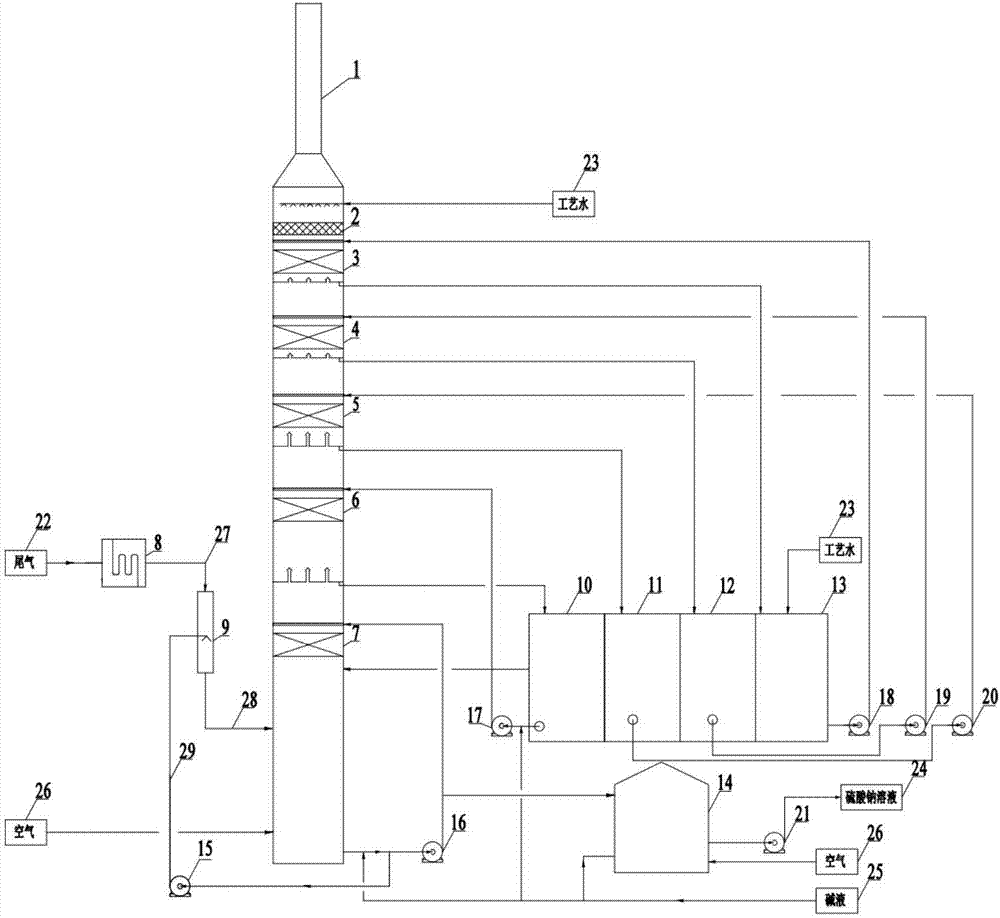
[0026] A method for exhaust gas desulfurization, including heat exchange, absorption, oxidation and circulation parts.

[0027] figure 1 In , the direction of the arrow indicates the flow direction of gas or liquid. like figure 1 As shown, the heat exchange is mainly carried out in the flue gas heat exchanger 8 and the quenching section 9 . High SO from sulfur recovery 2 Concentrated high-temperature waste gas 22 first passes through the flue gas heat exchanger 8 for heat exchange, and the waste gas is reduced from 300°C to 220°C. The exhaust gas 27 after cooling enters from the top of the quenching section 9, which is a vertical spray pipe, and the absorption liquid at the bottom of the tower is transported to the quenching section 9 by the quenching circulating pump 15 as the quenching circulating liquid 29 for spraying, and the gas-liquid two-phase Countercurrent contact, adiabatic saturation cooling of high-temperature exhaust gas, the exhaust gas is absorbed by adiaba...

Embodiment 2

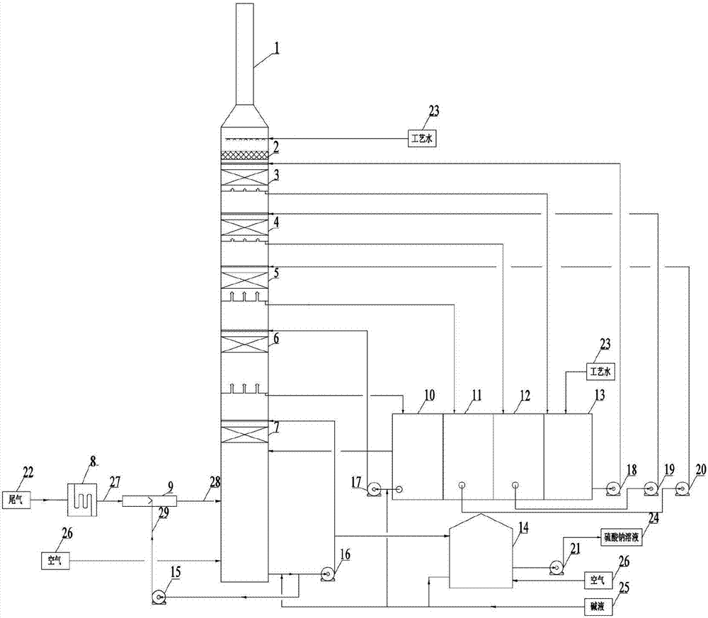
[0045] like figure 2 As shown, in addition to replacing the vertical spray pipe as the quenching pipe 9 with a horizontal spraying pipe in embodiment 1, the gas-liquid in the quenching pipe 9 is countercurrently contacted, and the absorption liquid circulation tank 10, the primary water circulation tank 11, Except that the secondary water circulation tank 12 and the tertiary water circulation tank 13 are arranged separately, the rest is the same as that of Embodiment 1, and will not be repeated here.


PUM


Abstract

The invention discloses a method for desulfurizing exhaust gas. The method comprises the following steps: firstly, carrying out heat exchange on the exhaust gas, and reducing the temperature to 190 to 250DEG C; secondly, enabling the exhaust gas subjected to heat exchange to enter a quench zone, enabling the exhaust gas to be in contact with absorption liquid, and then carrying out adiabatic saturation absorption on the exhaust gas so as to reduce the temperature of the exhaust gas to 60 to 80DEG C; thirdly, enabling the exhaust gas exhausted from the quench zone to enter a first absorption zone, enabling the exhaust gas to be in contact with sprayed absorption liquid in a filler and absorbing sulfur dioxide in the exhaust gas by the absorption liquid; fourthly, enabling the exhaust gas exhausted from the first absorption zone to enter a second absorption zone, enabling the exhaust gas to be in countercurrent contact with the sprayed absorption liquid in the filler, and removing all remaining sulfur dioxide from the exhaust gas; fifthly, carrying out multistage washing on the exhaust gas exhausted from the second absorption zone, and removing a salt solution entrained in the exhaust gas; sixthly, removing droplets in the exhaust gas exhausted from a multistage washing zone and then discharging. The method disclosed by the invention has the advantages that the operation is simple, operation expenses are reduced, the occupied area is greatly reduced, and emission indexes can be far lower than the environmental protection standard level; the method is in the leading level of technology.

Description

technical field [0001] The invention relates to a treatment method for waste gas, in particular to a treatment method for waste gas containing sulfur dioxide. Background technique [0002] Since the improved Claus sulfur recovery technology realized industrial production in the 1930s, after nearly 90 years of development and improvement, it has become mature and perfect. 300-800mg / Nm 3 , cannot meet the current standard requirements. [0003] At this stage, the reduction-absorption method is commonly used in the tail gas treatment of sulfur recovery units, that is, all the sulfur-containing compounds in the tail gas are first reduced to H 2 S, and then remove it, and finally recover it in the form of acid gas or elemental sulfur, and the absorption liquid can be recycled and used. SCOT is a typical reduction-absorption method. The main disadvantage of this process is that the equipment investment, operation cost and energy consumption are quite high. The oxidation-absorp...

Claims


Application Information

Patent Timeline
Patent Type & Authority Applications(China)
IPC IPC(8): B01D53/78B01D53/75B01D53/50B01D53/96F28C3/06
CPCB01D53/502B01D53/75B01D53/78B01D53/96F28C3/06B01D2251/304B01D2251/604
Inventor 李明军邢亚琴汪群刘芳张传玲张建超申晨黄建清
Owner SINOPEC NANJING ENG & CONSTR
Why Eureka
Try Eureka