Device and method for treating waste gas through high-energy ultraviolet light catalysis cooperated with ozone oxidation

An ozone oxidation and waste gas treatment device technology, applied in chemical instruments and methods, separation methods, dispersed particle separation, etc., can solve the problems of secondary pollution operation costs, low waste gas treatment efficiency, etc., and achieve light weight and low equipment energy consumption. , the effect of small equipment footprint

Inactive Publication Date: 2017-09-01
北京格朗德科技有限公司
View PDF10 Cites 10 Cited by
  • Summary
  • Abstract
  • Description
  • Claims
  • Application Information

AI Technical Summary

Problems solved by technology

[0005] The problems of the prior art solved by the present invention are: the existing technologies and devices for waste gas treatment generally have low treatment efficiency for waste gas, often produce secondary pollution or have extremely high operating costs

Method used


Image

  • Device and method for treating waste gas through high-energy ultraviolet light catalysis cooperated with ozone oxidation
  • Device and method for treating waste gas through high-energy ultraviolet light catalysis cooperated with ozone oxidation

Examples


Embodiment 1

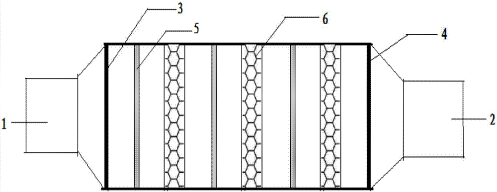
[0034] Embodiment 1 provides a waste gas treatment device for microwave stepless ultraviolet photocatalysis and ozone oxidation oxidation, such as figure 1 As shown, wherein, 1 is the air inlet, 2 is the air outlet, 3 is the first metal mesh, 4 is the second metal mesh, 5 is the photocatalyst layer, 6 is the ozone oxidation layer, wherein the first metal mesh and the second Metal nets are respectively arranged at the air inlet and the air outlet of the device. The photocatalyst layer and the ozone oxidation layer are provided with 3 cycles in the barrel of the device. That is, along the direction of gas flow, a photocatalyst layer, an ozone oxidation layer, a photocatalyst layer, an ozone oxidation layer, a photocatalyst layer, and an ozone oxidation layer are provided. The first metal mesh and the second metal mesh are respectively provided with nanoscale TiO 2catalyst of light. The nanoscale TiO 2 The photocatalyst is 50nm TiO 2 , purchased from Nanchang Chuangjie Techn...

Embodiment 2

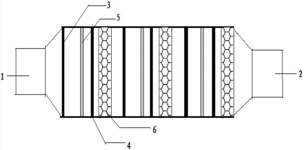
[0041] Embodiment 2 provides a waste gas treatment device for microwave stepless ultraviolet photocatalysis and ozone oxidation oxidation, such as figure 2 shown. Wherein 1 is an air inlet, 2 is an air outlet, 3 is a first metal mesh, 4 is a second metal mesh, 5 is a photocatalyst layer, and 6 is an ozone oxidation layer. The difference between Embodiment 2 and Embodiment 1 is that, in Embodiment 2, metal meshes are arranged before and after each photocatalyst layer, which are the first metal mesh and the second metal mesh respectively. That is, the first metal mesh, the photocatalyst layer, the second metal mesh and the ozone oxidation layer are sequentially arranged along the airflow direction, and this sequence is repeated three times. The wavelengths of the microwave electrodeless ultraviolet light are respectively set to 185nm, 253.7nm and 185nm, and then the same method as in Example 1 is used for measurement. The test shows that the removal rate of benzene is as high ...


PUM

PropertyMeasurementUnit
wavelengthaaaaaaaaaa

Abstract

The invention belongs to the technical field of air pollutant purification and specifically relates to a device and a method for treating waste gas through high-energy ultraviolet light catalysis cooperated with ozone oxidation. The device comprises a barrel body, wherein the barrel body is provided with a gas inlet (1) and a gas outlet (2), a photocatalyst layer (5) and an ozone oxidation layer (6) are sequentially arranged in the barrel body along the gas flowing direction, the photocatalyst layer (5) and the ozone oxidation layer (6) are arranged in the radial direction of the barrel body, the barrel body is provided with metal nets which are respectively arranged on the two sides of the photocatalyst layer (5), and a nanoscale TiO2 photocatalyst is arranged on the metal nets. When being used, the device can completely resolve toxic and harmful matters in industrial waste gas and can achieve a perfect deodorizing and purifying effect; the decomposed industrial waste gas can completely reach harmless discharge, secondary pollution is avoided, and meanwhile, a high-efficiency sterilizing and disinfecting effect is achieved.

Description

technical field [0001] The invention belongs to the technical field of air pollutant purification, and in particular relates to a device and method for treating waste gas by high-energy ultraviolet photocatalysis and ozone oxidation, in particular to a device and method for treating waste gas by using microwave ultraviolet photocatalysis and ozone oxidation. Background technique [0002] As people pay more attention to air quality, the problem of air pollution has become the most prominent and most concerned environmental problem in our country. In particular, volatile organic compounds often become the focus of air pollution prevention and control because of their irritation, toxicity and carcinogenicity. Volatile organic compounds are often produced in meat processing factories, pharmaceutical factories, electronics factories, paper mills, printing and dyeing factories, leather factories, feed factories, sewage plants, garbage factories, spice factories, essence factories,...

Claims


Application Information

Patent Timeline
Patent Type & Authority Applications(China)
IPC IPC(8): B01D53/86B01D53/74B01D53/88B01D53/52B01D53/58B01D53/48B01D53/72B01D53/66B01D53/44A61L9/20
CPCB01D53/86A61L9/205B01D53/74B01D53/8603B01D53/8612B01D53/8634B01D53/8668B01D53/8675B01D53/8687B01D53/88B01D2255/20707B01D2255/802
Inventor 罗强音
Owner 北京格朗德科技有限公司
Why Eureka
Try Eureka