
Supercritical-carbon-dioxide circulating fluidized bed boiler heating system and heating method

A carbon dioxide and heating system technology, which is applied in the direction of indirect carbon dioxide emission reduction, fluidized bed combustion equipment, combustion methods, etc., can solve the problems of increased difficulty in superheater layout, high exhaust gas temperature, and easy overheating, and achieves compact structure, Uniform heating, saving floor space

Active Publication Date: 2017-09-01
SHANDONG UNIV
View PDF9 Cites 7 Cited by
  • Summary
  • Abstract
  • Description
  • Claims
  • Application Information

AI Technical Summary

Problems solved by technology

For small-capacity (400°C), and its specific heat is lower than that of water vapor, which makes the tube wall of the radiation heating surface in the furnace easy to overheat, and also makes higher exhaust temperature

Method used


Image

  • Supercritical-carbon-dioxide circulating fluidized bed boiler heating system and heating method
  • Supercritical-carbon-dioxide circulating fluidized bed boiler heating system and heating method

Examples


Embodiment 1

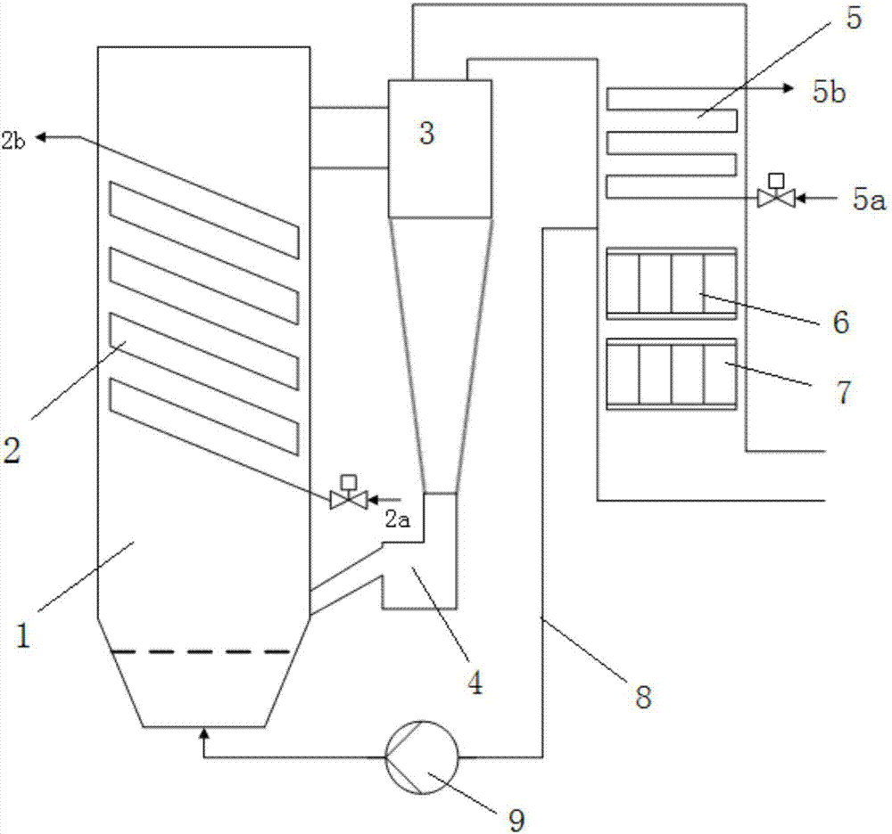
[0043] Such as figure 1 As shown, a small supercritical carbon dioxide circulating fluidized bed boiler device includes a boiler furnace 1, a spiral coil superheater 2, a cyclone separator 3, a return valve 4, a convection superheater 5, and a primary air preheater 6 , secondary air preheater 7, recirculation flue 8, recirculation fan 9 and connecting pipes.

[0044]A semi-buried tube spiral coil superheater 2 is arranged in the furnace wall of the boiler furnace 1, the working medium inlet 2a of the spiral tube superheater is arranged at the lower part of the furnace, the working medium outlet 2b of the spiral tube superheater is arranged at the upper part of the furnace, and the heat exchange coil The number is 1.5-2 circles. The flue gas outlet at the upper part of the boiler furnace 1 is connected to the inlet of the cyclone separator 3, the solid particle outlet at the lower part of the cyclone separator 3 is connected to the inlet of the return valve 4, and the outlet o...

Embodiment 2

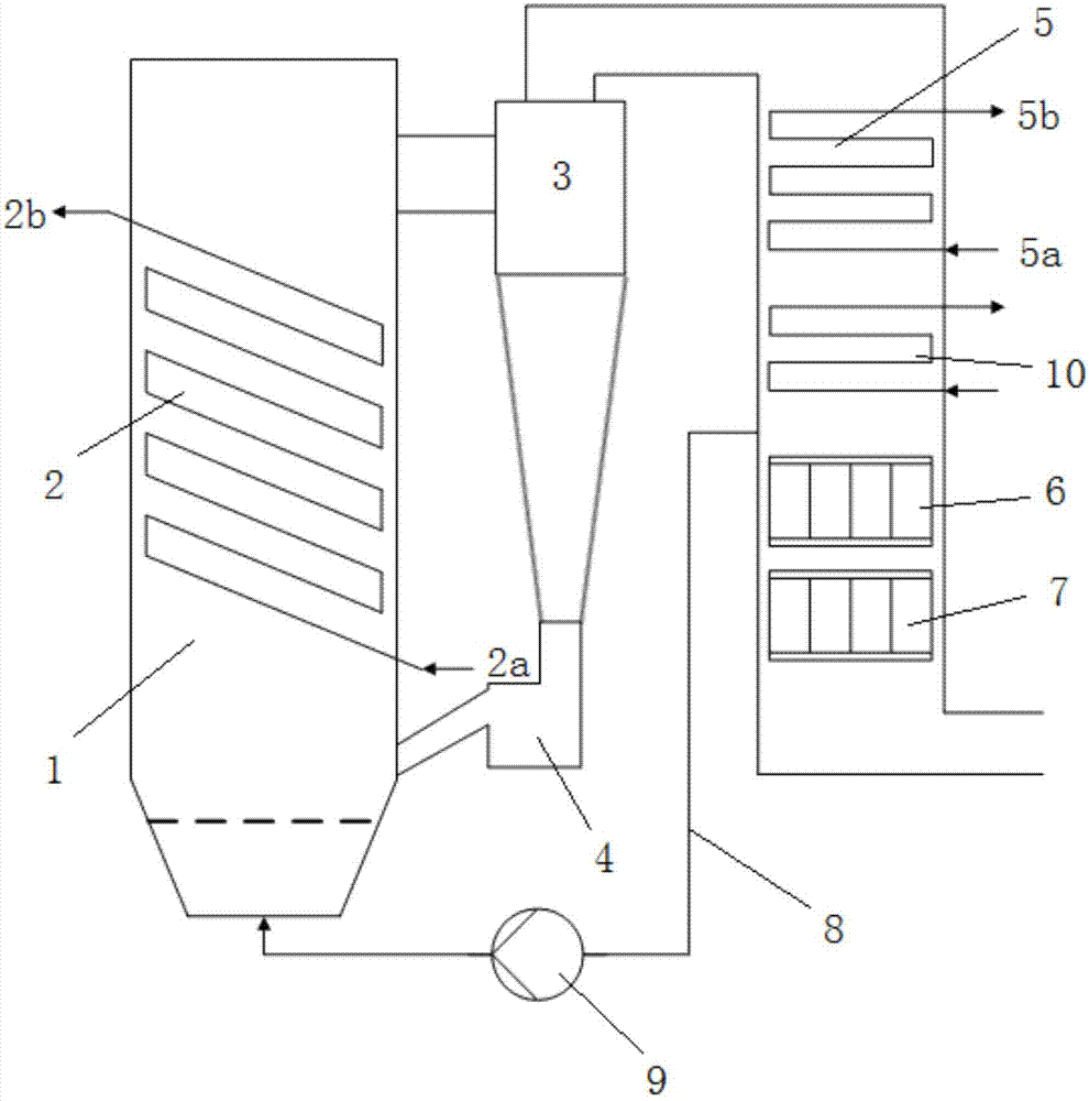
[0048] Such as figure 2 As shown, a small supercritical carbon dioxide circulating fluidized bed boiler device includes a boiler furnace 1, a spiral coil superheater 2, a cyclone separator 3, a return valve 4, a convection superheater 5, and a secondary air preheater 6 , Primary air preheater 7, recirculation flue 8, recirculation fan 9, split economizer 10 and connecting pipes.

[0049] The difference between this embodiment and embodiment 1 is:

[0050] The spiral coil superheater and the convective superheater are connected in series, the working medium outlet 2b of the spiral coil superheater is connected with the working medium 5a of the convective superheater, and the supercritical carbon dioxide working fluid entering the boiler passes through the spiral coil superheater 2 and the convective superheater successively. device 5. In the tail flue, a split economizer 10 is arranged between the convection superheater 5 and the secondary flue gas preheater 6, and the recir...


PUM


Abstract

The invention discloses a supercritical-carbon-dioxide circulating fluidized bed boiler heating system and a heating method. The supercritical-carbon-dioxide circulating fluidized bed boiler heating system comprises a boiler, a spiral tube coil super-heater, a classifier, a gas pass and a convection super-heater, wherein the spiral tube coil super-heater is mounted in a boiler chamber of the boiler, and of a spiral tube coil structure, and a spiral tube coil provides a supercritical-carbon-dioxide circulating channel; the convection super-heater is mounted in the gas pass, and provides a supercritical-carbon-dioxide circulating channel; the upper end of the boiler chamber communicates with an inlet of the classifier, an smoke outlet of the classifier communicates with one end of the gas pass, and an solid-particle outlet of the classifier communicates with the boiler chamber of the boiler through a refeed valve; and the spiral tube coil super-heater and the convection super-heater are arranged in parallel or in series.

Description

technical field [0001] The invention belongs to the technical field of high-efficiency thermal power generation, and in particular relates to a supercritical carbon dioxide circulating fluidized bed boiler heating system and a heating method. Background technique [0002] The power cycle is the core and foundation of thermal power generating units, and improving cycle efficiency is an eternal goal pursued by the power industry. Conventional thermal power units mostly use steam Rankine cycle, and the key determinant of its efficiency is the main steam parameters. At present, the efficiency of the most advanced 700°C ultra-supercritical unit can theoretically exceed 50%. However, limited by existing materials and processes, the improvement of steam parameters has its limits and the cost is high. How to realize the innovation and breakthrough of power cycle technology on the basis of the existing technical level has important practical and long-term significance for the sustai...

Claims


Application Information

Patent Timeline
Patent Type & Authority Applications(China)
IPC IPC(8): F23C10/18F23L15/00
CPCF23C10/18F23L15/00Y02E20/34
Inventor 徐震王志强马春元董勇
Owner SHANDONG UNIV
Learn More