Muck improving system of multi-cutter tunnel boring machine

A technology for muck improvement and roadheader, which is applied in the direction of earth drilling, mining equipment, tunnels, etc., and can solve the problem of not being able to meet the requirements of multi-cutter roadheader construction, large particle size dregs are difficult to flow to the slag outlet, Local slag affects the excavation and other issues, and achieves the effects of reducing the internal friction angle, enhancing cohesion, and reducing surface settlement

Active Publication Date: 2017-09-08
CHINA RAILWAY ENGINEERING EQUIPMENT GROUP CO LTD
View PDF14 Cites 7 Cited by
  • Summary
  • Abstract
  • Description
  • Claims
  • Application Information

AI Technical Summary

Problems solved by technology

[0005]The excavation section of the multi-cutter header has a large span. When excavating in the upper soft and lower hard composite strata, the stratum conditions of each cutter head are different. Similarly, the types of modifiers that need to be injected into each cutterhead during excavation will also be different; the feed port of the screw conveyor used for slag discharge of the multi-cutterhead roadheader is not at the lowest point in the structure, and it is difficult to remove large-sized slag. Flow to the slag outlet, and then cause local slag to affect the excavation; multi-cutter roadheaders generally have excavation blind spots, which need to be dealt with by auxiliary measures; multi-cutter roadheaders are mostly used for shallow overburden excavation, and the thickness of the overburden layer is generally less than 5m , the top has high water permeability and strong air permeability, which is easy to cause surface subsidence and slurry leakage
Therefore, the traditional improvement method is not enough to meet the construction requirements of the multi-cutter header. Therefore, it is of great significance to invent a muck improvement system suitable for the multi-cutter header.

Method used


Image

  • Muck improving system of multi-cutter tunnel boring machine
  • Muck improving system of multi-cutter tunnel boring machine
  • Muck improving system of multi-cutter tunnel boring machine

Examples


Embodiment 1

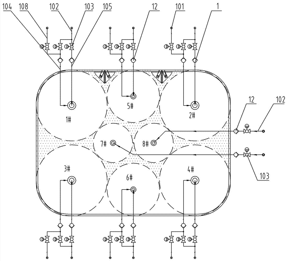
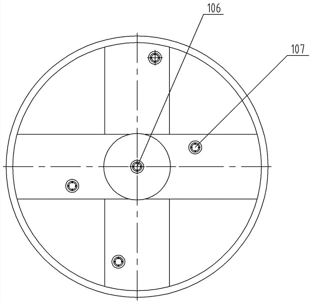
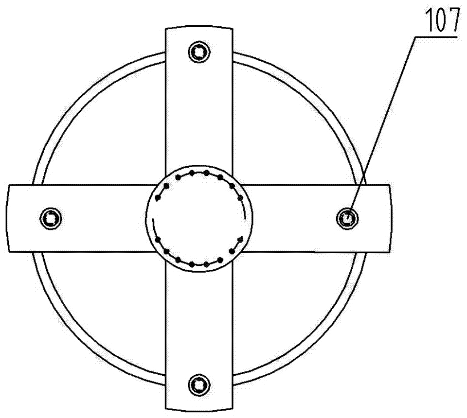
[0038] In the muck improvement system of the multi-cutter header of the present invention, the roadheader is an example of a roadheader with 8 cutter heads, wherein No. 7 and No. 8 cutter heads have a diameter of 1.2m, and each cutter head is provided with 4 nozzles around the cutter head. ; The diameters of No. 1, No. 2, No. 3, No. 4, No. 5 and No. 6 cutter heads are all greater than 1.2m, and each cutter head is equipped with 1 nozzle in the center of the cutter head and 4 nozzles around the cutter head.

[0039] The muck improvement system of the multi-cutterhead roadheader of the present invention includes a cutterhead improvement system 1, a clay injection system 2, an excavation blind area flushing system 3 and a general control mechanism, and the cutterhead improvement system 1 includes a plurality of parallel-connected Cutter unit improvement mechanism. Each cutter head of the multi-cutterhead roadheader is equipped with a set of independent cutter head unit improvement...


PUM


Abstract

The invention belongs to the technical field of tunnel engineering construction equipment, and particularly relates to a muck improving system of a multi-cutter tunnel boring machine. The muck improving system comprises a cutter improving system, a clay injecting system, an excavation dead zone scouring system and a general control mechanism, collaborative or independent working of the cutter improving system, the clay injecting system and the excavation dead zone scouring system is controlled by the general control system, the cutter improving system can realize injection of muck improvers for multiple cutters, the cutters are independent from each other, and different improvers can be selectively injected to the cutters; the clay injection system can inject clay to the top of a clay bin, the upper portion of a residue discharging port and areas prone to residue accumulation on two sides of the bottom of an anterior shield partition to respectively realize functions of supporting an arch crown, reducing jacking friction force and wrapping large-particle muck; the excavation dead zone scouring system realizes muck cutting of excavation dead zones and assists in muck improving through high-pressure water.

Description

technical field [0001] The invention belongs to the technical field of tunnel engineering construction equipment, and in particular relates to a dreg improvement system of a multi-cutter head boring machine. Background technique [0002] Roadheader tunnel construction has the advantages of safety, high efficiency, and environmental protection, and has been widely used in railways, highways, hydropower, municipal, national defense and other fields. However, most of the current tunnel boring machines belong to the circular single-cutter type, and the multi-cutter boring machines are still in the initial development stage. Compared with the single-cutter header, the multi-cutter header has the advantages of low cost, suitable for excavation in shallow overlying soil, and can excavate any special-shaped section. Requirements for soil improvement are very high. [0003] The improvement of dregs is a key link in the construction process of the roadheader. The undisturbed soil ex...

Claims


Application Information

Patent Timeline
Patent Type & Authority Applications(China)
IPC IPC(8): E21D9/08E21D9/093
CPCE21D9/001E21D9/0678E21D9/08E21D9/093
Inventor 龚廷民贾连辉王小涛徐姣姣冯猛张九宇
Owner CHINA RAILWAY ENGINEERING EQUIPMENT GROUP CO LTD
Why Eureka
Try Eureka