Heavy-duty diesel engine split type rocker arm brake mechanism for commercial vehicle
A heavy-duty diesel engine and braking mechanism technology, applied in the direction of machine/engine, engine components, mechanical equipment, etc., can solve the problems of difficult assembly and maintenance, low light weight, poor braking effect, etc., to achieve convenient assembly and maintenance, The effect of high light weight and low cost
- Summary
- Abstract
- Description
- Claims
- Application Information
AI Technical Summary
Problems solved by technology
Method used
Image
Examples
Embodiment 1
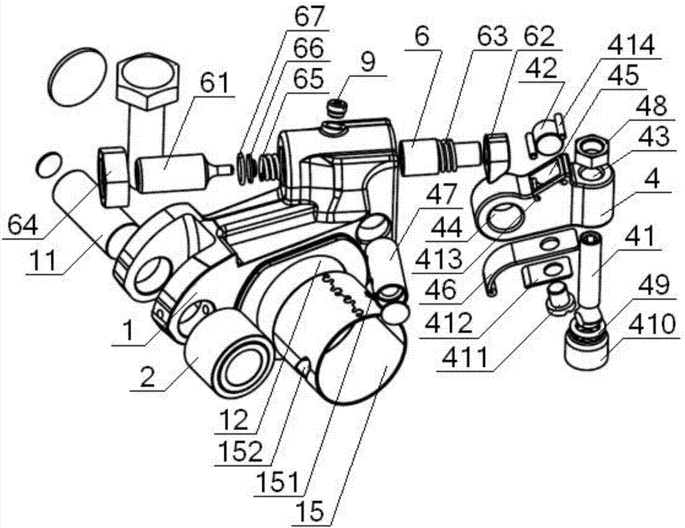
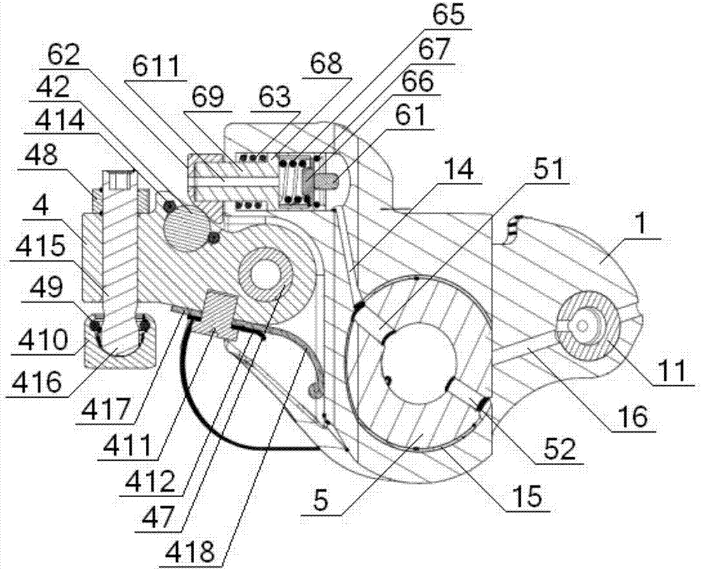
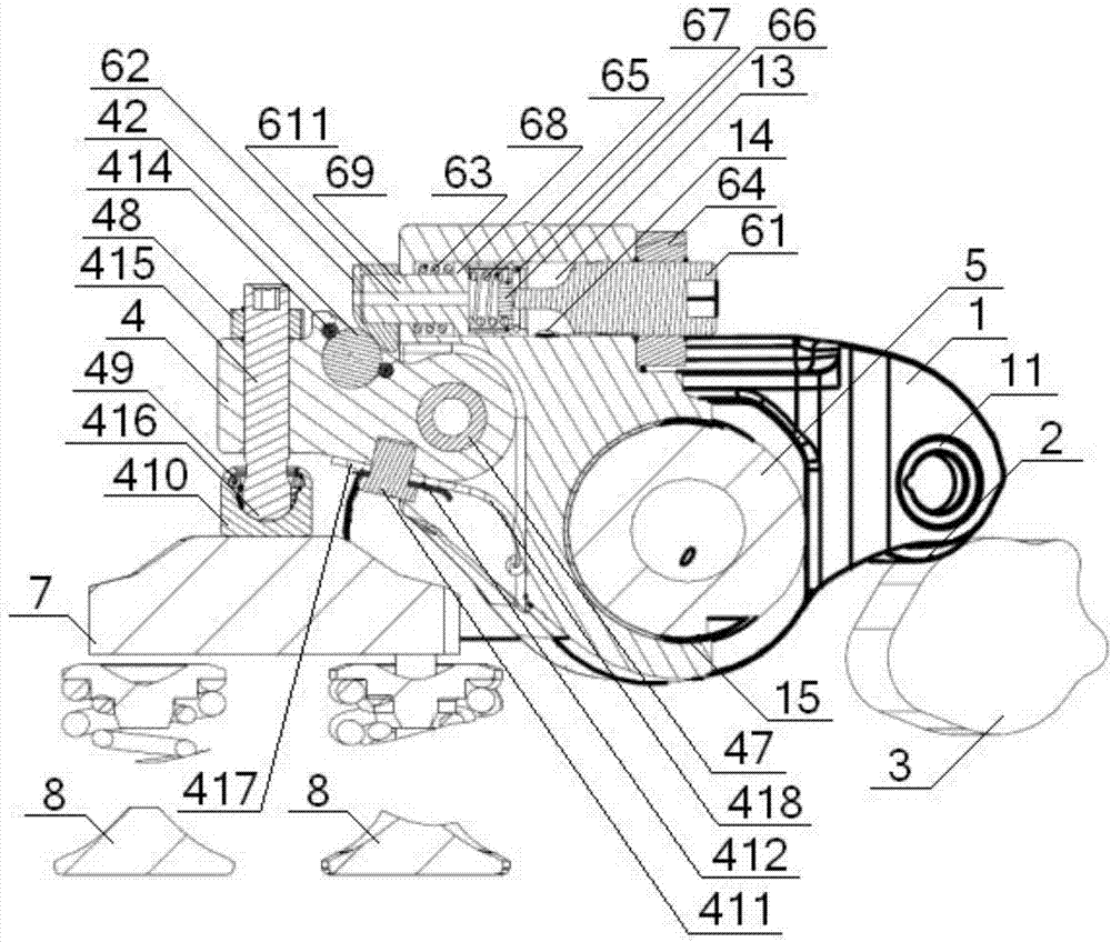
[0046] see Figure 1 to Figure 8, a commercial vehicle heavy-duty diesel engine split rocker brake mechanism, including a rocker body 1, one end of the rocker body 1 is hinged to a roller 2 through a first pin 11, and the roller 2 is in contact with a cam 3 , the other end of the rocker arm body 1 is provided with a swing mechanism, the middle part of the rocker arm body 1 is provided with a main mounting hole 12, and the rocker arm body 1 is installed on the rocker arm shaft 5 through the main mounting hole 12; The mechanism includes a swing head 4, a first adjusting bolt 41, and a roller 42. One end of the swing head 4 is provided with a mounting cavity 43, the other end of the swing head 4 is provided with a first mounting hole 44, and the middle of the swing head 4 is provided with a The second installation hole 45, the bottom of the swing head 4 is provided with a leaf spring 46, one end of the leaf spring 46 is fixed on the bottom of the swing head 4, and the other end o...
Embodiment 2
[0048] Basic content is the same as embodiment 1, the difference is:
[0049] see Figure 1 to Figure 8 , the leaf spring 46 includes a flat portion 417 and a curled portion 418, the flat portion 417 is fixed on the bottom of the swing head 4 by a spring fastening screw 411, and the curled portion 418 is press-fitted on the bottom of the rocker body 1; A spring pressing piece 412 is installed between the plane portion 417 and the spring fastening screw 411 , and an end of the spring pressing piece 412 close to the curled portion 418 is arranged in a curled shape.
Embodiment 3
[0051] Basic content is the same as embodiment 1, the difference is:
[0052] see Figure 1 to Figure 8 , the hydraulic system also includes an overload protection system, the overload protection system includes an overflow spring 65, a disc-shaped piston 66, a piston clip 67, a hydraulic chamber is arranged in the cylinder 68, the overflow spring 65, The disc-shaped piston 66 and the piston clamp 67 are all arranged in the hydraulic chamber, one end of the overflow spring 65 is in contact with the bottom of the hydraulic chamber, the other end of the overflow spring 65 is in contact with one end of the disc-shaped piston 66, and the disc-shaped piston 66 is in contact with the disc-shaped piston. The other end of the type piston 66 is in contact with the piston clip 67. The second adjusting bolt 61 includes a connected elongated tip and the adjusting bolt body. In contact with each other, an overflow groove 610 is arranged on the inner peripheral surface of the hydraulic cha...
PUM
 Abstract
Description
Claims
Application Information
 - R&D
- Intellectual Property
- Life Sciences
- Materials
- Tech Scout
- Unparalleled Data Quality
- Higher Quality Content
- 60% Fewer Hallucinations
Browse by: Latest US Patents, China's latest patents, Technical Efficacy Thesaurus, Application Domain, Technology Topic, Popular Technical Reports.
© 2025 PatSnap. All rights reserved.Legal|Privacy policy|Modern Slavery Act Transparency Statement|Sitemap|About US| Contact US: help@patsnap.com


