

An optical fiber manufacturing process
A manufacturing process and technology of optical fibers, applied in the field of optical communication, can solve the problems of concave optical fibers and protruding end faces of ceramic ferrules, and achieve the effects of uniform and full glue, improved bonding strength, and increased effective bonding area.
- Summary
- Abstract
- Description
- Claims
- Application Information
AI Technical Summary
Problems solved by technology
Method used
Image

Examples
Embodiment 1
[0038] like Figure 1-4 As shown, an optical fiber manufacturing process includes the following steps:
[0039] a. Cutting steps: cut the optical cable of the specified length;
[0040] b. Pretreatment step: the pretreatment step includes the step of drying the wire, the step of pressing the wire, and the step of peeling in sequence,
[0041] Drying step: bake the optical cable obtained in step a at high temperature, and then fully cool it at room temperature; in the drying step, the optical cable with the shrinkage rate of the outer sheath 1 material >1‰ is baked at a high temperature of 120 ° C for 6 hours, and the cooling time is 2.5 hours are handled;
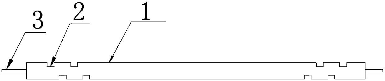
[0042] Crimping step: Add zigzag indentation to the surface of the outer sheath 1 of the optical cable after the drying step, see figure 1 , using a wire crimping machine to press out four pits 2 on the outer sheath 1, the four pits 2 are evenly distributed on the upper and lower parts of the optical cable sheath 1, and ...
Embodiment 2
[0050] like Figure 1-4 As shown, an optical fiber manufacturing process includes the following steps:
[0051] a. Cutting steps: cut the optical cable of the specified length;
[0052] b. Pretreatment step: the pretreatment step includes the step of drying the wire, the step of pressing the wire, and the step of peeling in sequence,
[0053] Drying step: bake the optical cable obtained in step a at high temperature, and then fully cool it at room temperature; in the drying step, the optical cable with the shrinkage rate of the outer sheath 1 material ≤ 1‰ is baked at a high temperature of 95°C for 6 hours, and the cooling time is 3.5 hours are handled;
[0054] Crimping step: Add zigzag indentation to the surface of the outer sheath 1 of the optical cable after the drying step, see figure 1 , using a wire crimping machine to press out four pits 2 on the outer sheath 1, the four pits 2 are evenly distributed on the upper and lower parts of the optical cable sheath 1, and th...
Embodiment 3
[0062] like Figure 1-4 As shown, an optical fiber manufacturing process includes the following steps:
[0063] a. Cutting steps: cut the optical cable of the specified length;
[0064] b. Pretreatment step: the pretreatment step includes the step of drying the wire, the step of pressing the wire, and the step of peeling in sequence,
[0065] Drying step: bake the optical cable obtained in step a at high temperature, and then fully cool it at room temperature; in the drying step, the optical cable with the shrinkage rate of the outer skin 1 material >1‰ is baked at a high temperature of 120 ° C for 6 hours, and the cooling time is 3.5 hours are handled;
[0066] Crimping step: Add zigzag indentation to the surface of the outer sheath 1 of the optical cable after the drying step, see figure 1 , using a wire crimping machine to press out four pits 2 on the outer sheath 1, the four pits 2 are evenly distributed on the upper and lower parts of the optical cable sheath 1, and th...
PUM
 Abstract
Description
Claims
Application Information