A bulb tubular hydroelectric generator

A water turbine generator and light bulb cross-flow technology, which is applied in the direction of electromechanical devices, electrical components, electric components, etc., can solve the problem of affecting the service life of each component of the generator, the narrow internal space of the main generator, and the unfavorable heat dissipation of the generator and other problems, to achieve the effects of excellent power supply quality, improved axial air volume distribution, and good bottoming performance

Active Publication Date: 2019-12-24
湖南云箭集团有限公司
View PDF9 Cites 0 Cited by
  • Summary
  • Abstract
  • Description
  • Claims
  • Application Information

AI Technical Summary

Problems solved by technology

The main generator is placed underwater in a closed structure similar to a light bulb. The collector ring carbon brush needs to be maintained and replaced frequently. At the same time, the carbon powder produced by the wear and tear of the carbon brush will pollute the main generator and damage the stator and rotor. Insulated and large-section excitation cables are required to guide the excitation current from the external excitation equipment to the bulb generator placed underwater, which increases the cost. At the same time, due to the small internal space of the main generator, the maintenance of the collector ring carbon brush is very difficult. However, the structure of using an AC exciter to achieve excitation occupies the ventilation duct of the generator and increases the wind resistance, which is not conducive to the heat dissipation of the generator during operation, and the dust pollutants during operation can easily enter the airtight In the self-circulation ventilation route, it directly affects the service life of each component of the generator
[0004] In the prior art, several optimized structural forms have been proposed for the bubble tubular hydro-generator set, but there are various problems: 1. The bulb tubular hydro-generator provided by CN201320462960.0 has centralized open ventilation and cooling system, its bubble head part is equipped with a bubble head top flange that divides the bubble head into a cold air chamber and a hot air chamber; the front frame part of the stator base is provided with a front windshield that divides the front frame into a cold and hot air channel Plate, rear cold wind baffle and rear hot air baffle; inside the stator base, there are vertical wind baffles and rotor brackets that divide the interior of the stator base into cold air chambers and hot air chambers. Unified layout, the cold air and hot air of the unit are integrated and summarized separately. However, the ventilation and cooling system of this design has a long flow path for the cold air to pass through, which directly affects the efficiency of taking away heat through the wind, and its cooling effect is poor. , and it is difficult to maintain and overhaul; 2. CN201520299507.1 provides a straight-through cooling tubular turbine generator ventilation device, the hot air from the air outlet in the tubular unit is assembled through the draft plate, the intermediate ring, and the intermediate ring The windshield is introduced into the cooler to cool down, and the cooled cold air is sucked into the rotor bracket of the generator by the inclined air flow machine through the air guide tube, and the windshield, the rotor bracket and the rotor windshield form a windshield structure, so that It forms an air circulation system with the cooling channel. However, in the actual application process of the generator ventilation device with this structure, after the air passes through multiple working areas, it carries the particles brought by the working parts due to wear during work, and directly Through the closed ventilation and cooling circulation system, it enters the working area again, which accelerates the wear of the working parts, reduces the service life of the whole set of equipment, and has a large safety hazard; 4. A large bulb type water wheel provided by CN201210471881.6 The disc-shaped front frame of the generator, the brake needs to be assembled with the disc-shaped front frame of the bulb tubular hydroelectric generator first, and then installed and fixed with the bulb tubular type frame together with it , it is required that the assembly precision of the disc-shaped front frame is high during the hoisting process, and the brakes need to be fully protected during the on-site installation process to avoid damage to the brakes during the hoisting process. The installation process is very cumbersome. And in the follow-up inspection and maintenance process, it is necessary to disassemble the disc-shaped front frame, which has a huge amount of work and increases the maintenance cost of the whole set of equipment; 5. A hydroelectric generator provided by CN201010297664. , lower frame, braking device, electric output device, pulley, generator body; the middle part of the generator body is provided with a main shaft; a part of the main shaft extends out of the generator body, and a pulley is provided at its outer end; The part is arranged inside the generator body, and a flywheel is arranged in the middle part; the flywheel drives the rotor to rotate; the stator is arranged on the outside of the rotor; the braking device is connected with the rotor, and moving the braking device can increase its contact with the rotor The friction of the rotor stops the rotation of the rotor. However, the brake with this structure also requires high installation accuracy and is fixed on the parts. In the interior of the machine, other parts need to be disassembled in the subsequent inspection and maintenance process, and the engineering volume is huge, which increases the maintenance cost of the whole set of equipment

Method used


Image

  • A bulb tubular hydroelectric generator
  • A bulb tubular hydroelectric generator
  • A bulb tubular hydroelectric generator

Examples


Embodiment Construction

[0050] The present invention will be further described in detail and completely below in conjunction with the embodiments and the accompanying drawings.

[0051] For the convenience of description, spatially relative terms may be used here, such as "on ...", "over ...", "on the surface of ...", "above", etc., to describe the The spatial positional relationship between one device or feature shown and other devices or features. It will be understood that the spatially relative terms are intended to encompass different orientations of the device in use or operation in addition to the orientation depicted in the figures. For example, if the device in the figures is turned over, devices described as "above" or "above" other devices or configurations would then be oriented "beneath" or "above" the other devices or configurations. under other devices or configurations”. Thus, the exemplary term "above" can encompass both an orientation of "above" and "beneath". The device may be o...


PUM


Abstract

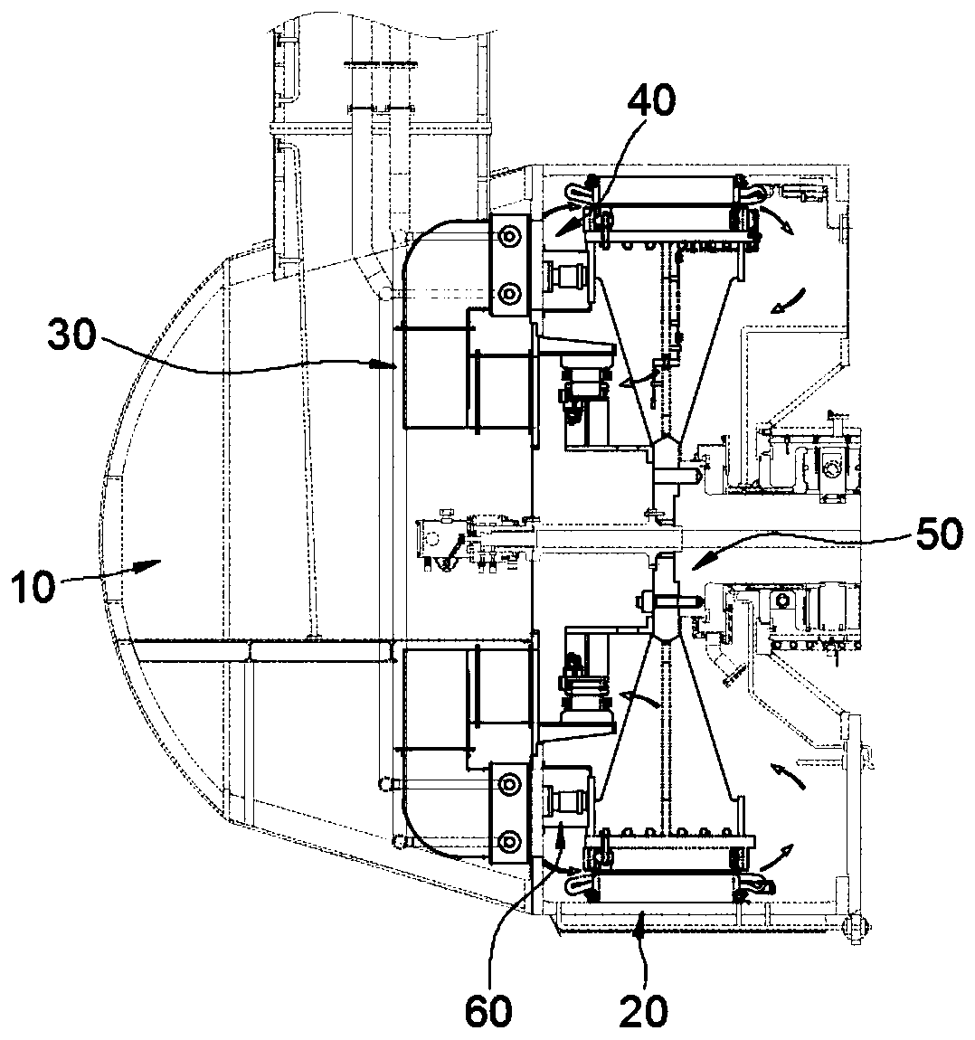
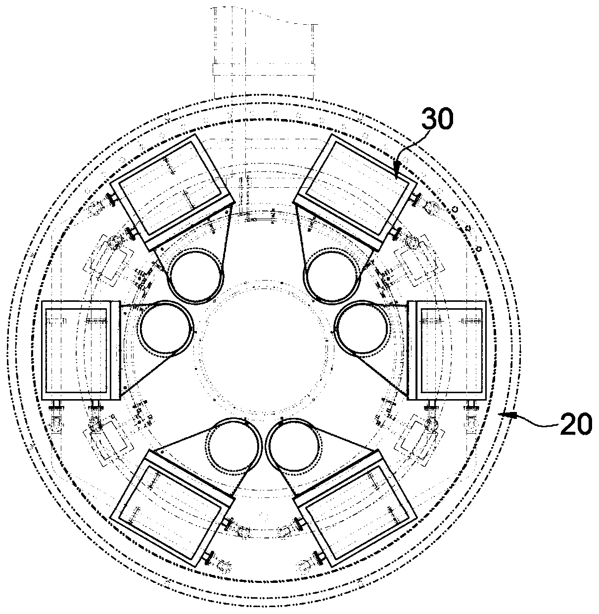
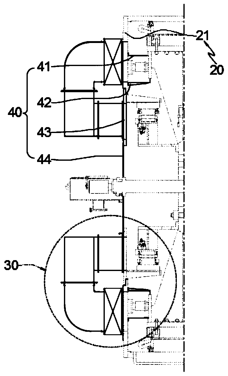
The invention provides a bulb tubular hydraulic generator, and belongs to the technical field of hydroelectric power generation equipment. The bulb tubular hydraulic generator comprises a bulb head and a stator frame integrally fixed and arranged in a co-movable manner, a generator body fixed in the stator frame, a stator upstream flange clamped between the stator frame and the bulb had, at least a group of ventilation assembly, and at least one group of wind screen assembly, a plurality of ventilation assemblies are fixed on the stator upstream flange and uniformly distributed at intervals in a co-circumferential manner, the wind screen assemblies are detachably fixed in the stator frame, the wind screen assemblies and the stator upstream flange are constructed to form a single-circulation air supply unit in which the wind screen assemblies communicate with the ventilation assemblies and the wind screen assemblies and the ventilation assemblies are mutually independent, the generator body comprises excitation assemblies, and the excitation assemblies and the stator frame are arranged in a coaxial manner. According to the bulb tubular hydraulic generator, brushless double-frequency generation can be realized, brushless variable-frequency generation can also be realized, the energy consumption of the whole ventilation system is reduced, the axial air quantity distribution can be effectively improved, and the ventilation and heat radiation effects of a unit can be improved.

Description

technical field [0001] The invention relates to a bulb tubular hydroelectric generator, in particular, it relates to a generator capable of realizing brushless dual-frequency power generation and brushless frequency conversion power generation; Realize brushless, no need for slip ring brushes, no high-frequency interference of sparks, no wear of slip rings and carbon brushes, and a bulb tubular hydro-generator with strong ventilation and cooling effects. Background technique [0002] The bulb tubular turbine is one of the important types of tubular turbines. Its applied water head is generally below 25m. It is mainly used in tidal power stations and low-head power stations on rivers. Generally, the generator and the turbine are directly connected. The generator is installed in inside the bulb. Because of its structure, it basically runs through the axial direction from the water inlet to the water outlet, without turning, the size of the flow channel is large and short, the...

Claims


Application Information

Patent Timeline
Patent Type & Authority Patents(China)
IPC IPC(8): H02K9/04H02K9/08
CPCH02K9/04H02K9/08
Inventor 王鲁军
Owner 湖南云箭集团有限公司
Why Eureka
Try Eureka