Isolated DC-DC boost converter with pull-down active clamping branch circuits

A boost converter, DC-DC technology, applied in the field of electricity, can solve the problems of low utilization rate of the magnetic core, difficulty in increasing the power, and easy saturation of the magnetic core, so as to improve the overall efficiency, reduce the conduction loss, and improve The effect of circuit gain

Inactive Publication Date: 2017-09-08
青岛中科德能光电科技有限公司
View PDF5 Cites 12 Cited by
  • Summary
  • Abstract
  • Description
  • Claims
  • Application Information

AI Technical Summary

Problems solved by technology

[0004] The traditional isolated DC-DC boost converter topology circuit has five forms: forward type, flyback type, half-bridge type, full-bridge type, and push-pull type. Among them, the structure of the forward type and flyback type circuits is simple, Low cost and easy to control, but there are disadvantages such as one-way excitation of the transformer, easy saturation of the magnetic core, low utilization rate of the magnetic core, difficulty in increasing the power, and difficulty in realizing soft switching control; the two-way excitation of the transformer in the half-bridge and full-bridge circuits, The utilization rate of the magnetic core is high, and the power can be increased, but there is a bias problem, and the upper and lower bridge arms are easy to pass through, the circuit control is relatively difficult, and the reliability is low; the transformer of the push-pull circuit is also bidirectionally excited, and there is no direct connection between the up

Method used


Image

  • Isolated DC-DC boost converter with pull-down active clamping branch circuits
  • Isolated DC-DC boost converter with pull-down active clamping branch circuits
  • Isolated DC-DC boost converter with pull-down active clamping branch circuits

Examples


Embodiment

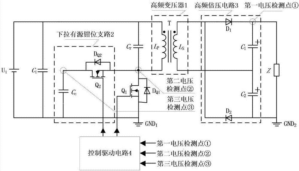
[0020] The main structure of the isolated DC-DC boost converter with pull-down active clamping branch described in this embodiment includes the input voltage U i , capacitance C i , Resonant capacitance C r , high-frequency transformer 1, the main switch tube Q 1 , the first diode D Q1 , pull-down active clamping branch 2, high-frequency voltage doubler circuit 3, equivalent load Z and control drive circuit 4; the first diode D Q1 main switch Q 1 of antiparallel diodes, the input voltage U i Through capacitance C i After filtering, the main switch Q 1 , the first diode D Q1 and pull-down active clamping branch 2 to invert the direct current into high-frequency alternating current, and the high-frequency alternating current is applied to the primary side inductance L P Both ends of the secondary side inductance L S The high-frequency AC voltage is induced at both ends, and supplies power to the equivalent load Z after passing through the high-frequency voltage doubler ...


PUM


Abstract

The invention belongs to the technical field of electricity, and relates to an isolated DC-DC boost converter with pull-down active clamping branch circuits. On the basis of a single-ended flyback type circuit topology, a resonant capacitor is connected in parallel on the primary side of a transformer, the pull-down active clamping branch circuits are in parallel connection at two ends of a drain source of a main switch tube; a high-frequency voltage doubling circuit is in cascade connection on the secondary side of the transformer; resonance oscillation is carried out on the resonant capacitor and an inductor on the primary side of the transformer which are in parallel connection, so that an original circuit becomes into bidirectional excitation, the utilization rate of a magnetic core is improved, and the voltage gain of isolated converter output for input is improved; the switching period of an auxiliary switch tube is the same as that of a main switch tube in the active clamping branch circuits, but each switching period of the auxiliary switch tube is a small period of time for conduction, the conduction loss is greatly reduced, the main switch tube and the auxiliary switch tube can realize soft switching, and a direct connection problem does not exist; asymmetrical voltage output by a secondary side winding of the transformer is effectively utilized through the high-frequency voltage doubling circuit in cascade connection on the secondary side of the transformer, so that the overall efficiency of the converter is improved.

Description

[0001] Technical field: [0002] The invention belongs to the technical field of electricity, and relates to an isolated direct current-direct current (DC-DC) boost converter, in particular to an isolated DC-DC boost converter with a pull-down active clamping branch. [0003] Background technique: [0004] The traditional isolated DC-DC boost converter topology circuit has five forms: forward type, flyback type, half-bridge type, full-bridge type, and push-pull type. Among them, the structure of the forward type and flyback type circuits is simple, Low cost and easy to control, but there are disadvantages such as one-way excitation of the transformer, easy saturation of the magnetic core, low utilization rate of the magnetic core, difficulty in increasing the power, and difficulty in realizing soft switching control; the two-way excitation of the transformer in the half-bridge and full-bridge circuits, The utilization rate of the magnetic core is high, and the power can be incr...

Claims


Application Information

Patent Timeline
IPC IPC(8): H02M3/335H02M1/38
CPCH02M1/38H02M3/33569H02M1/0058Y02B70/10
Inventor 王春芳赵永强孙华海
Owner 青岛中科德能光电科技有限公司
Why Eureka
Try Eureka