
Method and device for designing and optimizing passive vibration controller for fluid conveying pipe vibration control

A passive vibration and vibration control technology, used in design optimization/simulation, multi-objective optimization, computer-aided design, etc. And high-efficiency vibration control, reducing the difficulty of installation and use, the effect of simple controller structure

Active Publication Date: 2017-09-15
DALIAN UNIV OF TECH
View PDF5 Cites 7 Cited by
  • Summary
  • Abstract
  • Description
  • Claims
  • Application Information

AI Technical Summary

Problems solved by technology

[0002] Flow pipes have important application value and a wide range of applications in the industrial field. For example, in heat exchange, fuel transportation, hydraulic pressure and other fields, pipelines are used to transport fluids with a wide range of flow rates. Changes in fluid flow rates will induce excessive vibration in the pipelines. In turn, mechanical failures such as noise, material fatigue, and liquid leakage will occur, causing the equipment to fail to meet the required performance indicators
In terms of vibration control of flow pipes, there are two methods: active control and passive control. Although the control effect of the active control method is better, it has not been widely used because of the need for additional energy input and sensors; and the general passive vibration control The controller also has the disadvantages of large mass, poor control effect and long control process. In order to reduce the structural quality of the vibration controller and improve the suppression effect on pipeline vibration, based on the nonlinear targeted energy transfer theory and parallel nonlinear energy wells (parallel nonlinear energy sinks), designed a passive vibration controller to suppress excessive pipeline vibration
Judging from the existing literature, there are two important problems about the passive vibration controller of the flow pipe: first, the mass of the controller is relatively large, usually accounting for more than 10% of the total mass of the pipeline and the fluid, which is a serious limitation The scope of application of the passive vibration controller is defined; 2. Usually, the adaptability of the passive vibration controller is relatively poor, that is, the vibration control effect is only good in a very narrow flow rate range.
So far, no patent discloses the design and optimization of this type of passive vibration controller

Method used


Image

  • Method and device for designing and optimizing passive vibration controller for fluid conveying pipe vibration control
  • Method and device for designing and optimizing passive vibration controller for fluid conveying pipe vibration control
  • Method and device for designing and optimizing passive vibration controller for fluid conveying pipe vibration control

Examples


Embodiment Construction

[0037]The specific implementation of the present invention will be further described below in conjunction with the accompanying drawings and the simulation verification analysis process of the passive vibration controller.

[0038] The concrete case verification of the present invention is carried out at the emulation process of flow pipe---passive vibration controller system, detailed design steps are as follows:

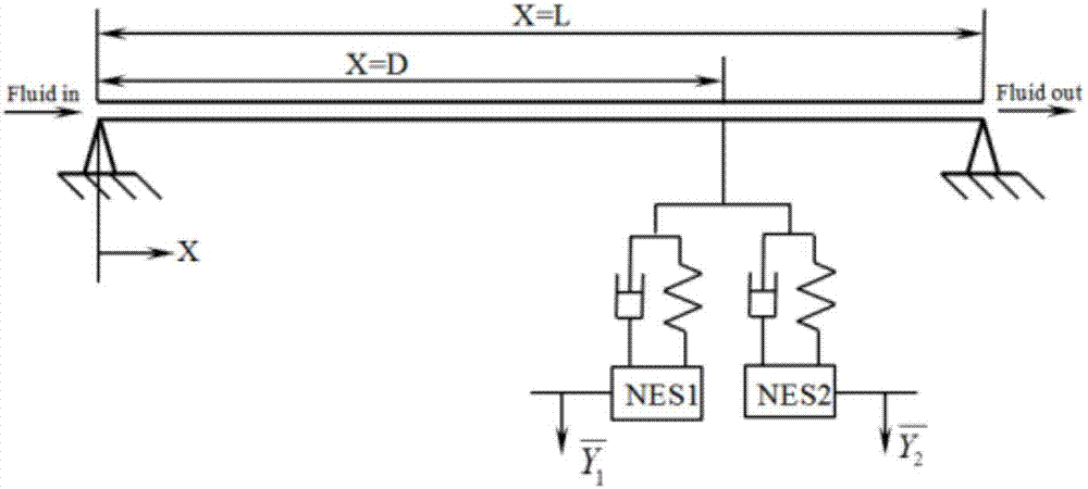
[0039] Step 1: Establish the mathematical model of the flow pipe-passive vibration controller, its physical structure is as follows figure 1 As shown, it is mainly composed of a flow pipe simply supported at both ends and a passive vibration controller connected to the pipe. The passive vibration controller is used to absorb the vibration energy generated when the fluid enters the pipeline. If gravity, internal damping, external tension and pressurization effects are not considered, the motion equation of the duct-passive vibration controller system can be written...


PUM


Abstract

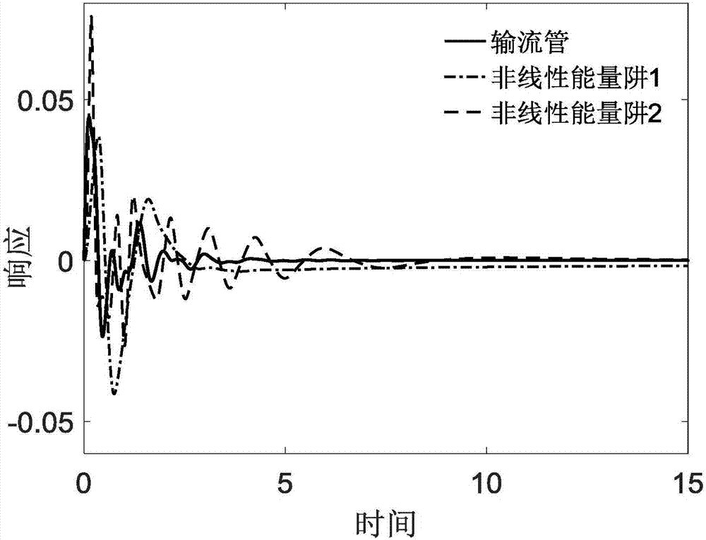
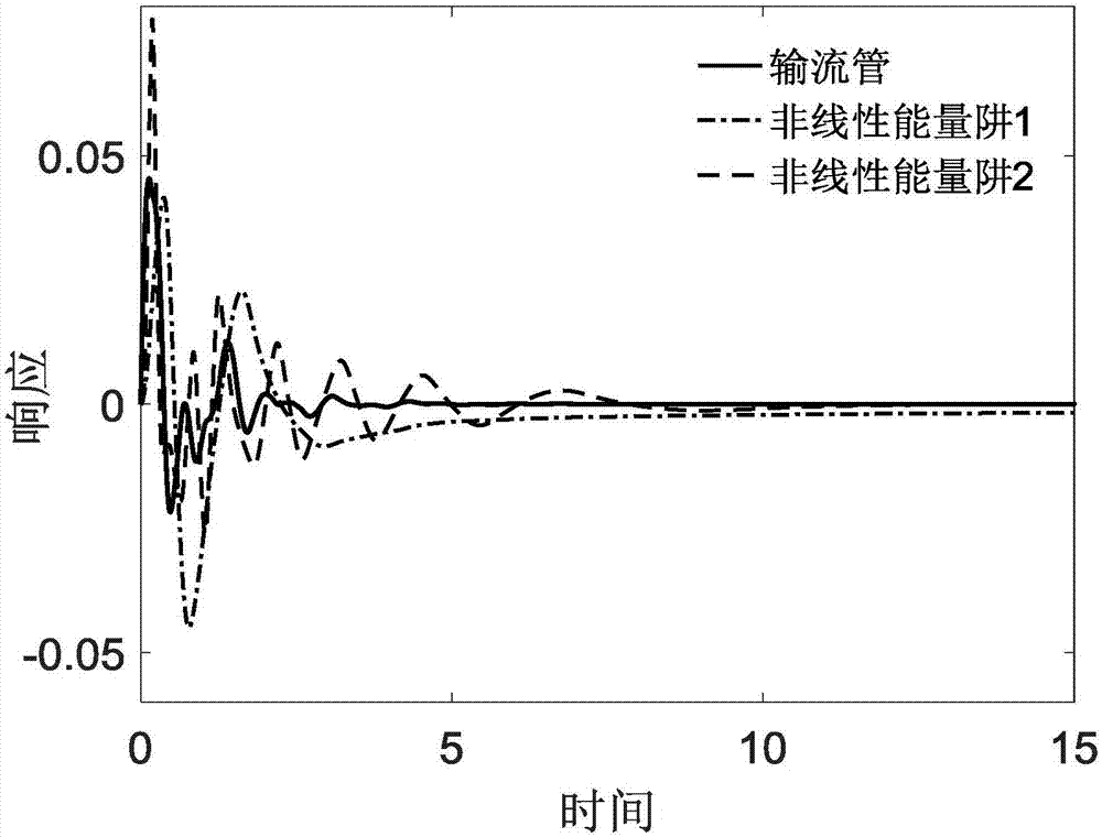
The invention discloses a method for designing and optimizing a passive vibration controller for fluid conveying pipe vibration control, and aims at solving the excessive vibration problem of fluid conveying pipes, providing the advantages of being free of external energy input and simple in installation operation, and breaking through the problem that the passive controller are relatively large in mass. The passive controller consists of parallel nonlinear energy traps; in order to verify the vibration control effect of the vibration controller, a mathematic model of a fluid conveying pipe-vibration controller system is established on the basis of a target energy transfer theory; and after dimension reduction and discretization are carried out on a dimensionless model through a standard Galerkin method, numerical simulation of the system is completed under a boundary condition of the system. Results indicate that the vibration controller is capable of rapidly and effectively dissipating the vibration energy of the fluid conveying pipes via a mass which is 5% of the mass of the whole system. Finally, the control is optimized through a ratio function of the energy dissipated by the controller and the total energy of the system; and the optimization result indicates that the precision requirement for mounting positions is not high in a certain range.

Description

technical field [0001] The invention proposes a passive vibration controller with self-adaptive characteristics for suppressing the vibration of the flow pipe, and carries out corresponding design and optimization on it, which belongs to the field of vibration control and simulation in structural strength analysis and test. Background technique [0002] Flow pipes have important application value and a wide range of applications in the industrial field. For example, in heat exchange, fuel transportation, hydraulic pressure and other fields, pipelines are used to transport fluids with a wide range of flow rates. Changes in fluid flow rates will induce excessive vibration in the pipelines. In turn, mechanical failures such as noise, material fatigue, and liquid leakage will occur, causing the equipment to fail to meet the required performance indicators. In terms of vibration control of flow pipes, there are two methods: active control and passive control. Although the control...

Claims


Application Information

Patent Timeline
Patent Type & Authority Applications(China)
IPC IPC(8): G06F17/50
CPCG06F30/20G06F2111/06G06F2113/14
Inventor 段楠孙希明杜宪李玉鹏仲崇权
Owner DALIAN UNIV OF TECH
Learn More