UV curing device for groove body printing
A technology of curing device and tank body, which is applied to the general parts of printing machinery, printing, printing machines, etc., can solve the problems that workpieces with grooves cannot be processed, the temperature is lowered, and no solution is given, so as to achieve reduction Effects of heat radiation, deformation prevention, and wrinkling prevention
- Summary
- Abstract
- Description
- Claims
- Application Information
AI Technical Summary
Problems solved by technology
Method used
Image

Examples
Embodiment 1
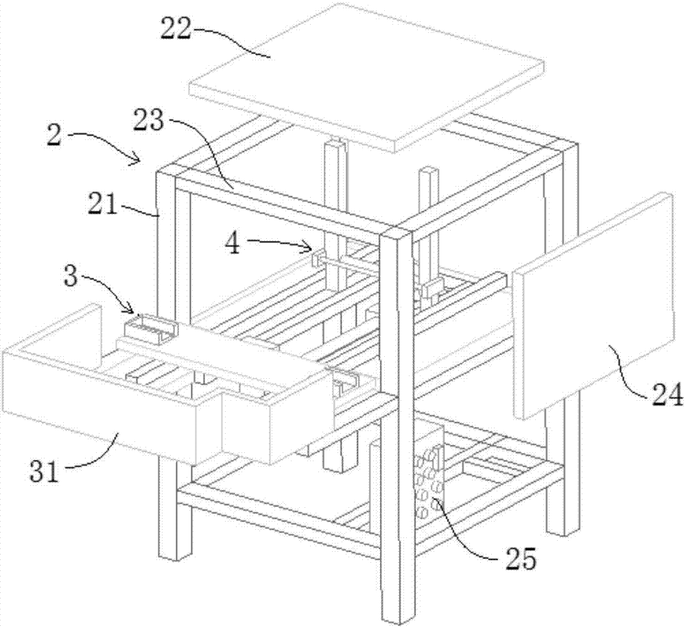
[0037] combine image 3 , Figure 4 , a UV curing device for tank printing in this embodiment is mainly composed of a support mechanism 2, a positioning feeding mechanism 3 and a light curing mechanism 4. The support mechanism 2 is used to form an integral bracket and form a closed space. Cured by light.
[0038] Specifically, the support mechanism 2 includes a support frame 21, a top plate 22 and a side wall plate 24. The support frame 21 is a frame structure for supporting other parts. For the required enclosed space, it can be surrounded by the top plate 22 and the side wall plate 24. into, and reserve a feed port for the entry and exit of workpiece 1. The required electric control box 25, switches, etc. can be arranged on the support frame 21, and there is no specific requirement for the specific shape and structure of the support frame 21. The above-mentioned top board and side wall boards are only described in conjunction with the accompanying drawings, and their spec...
Embodiment 2
[0050] A kind of UV curing device for groove body printing of this embodiment, its basic structure is identical with embodiment 1, and its difference is: the lamp tube support 41 of this embodiment is connected with cooling water pipe 43, and this cooling water pipe 43 Connected to the circulating water system. This cooling water pipe 43 can be arranged in parallel with the UV lamp tube 42, and is positioned at the cooling water pipe 43 rear, can cool the air in the groove by the cooling water pipe 43, because the cooling water pipe 43 is positioned at the UV lamp tube 42 rear, can not block the light.
Embodiment 3
[0052] A kind of UV curing device that is used for groove body printing of this embodiment, its basic structure is identical with embodiment 1, and its difference is: the lamp tube support 41 of this embodiment is connected with shading plate 44, and this shading plate 44 It is located on the lower side of the UV lamp 42 and is used to limit the irradiated area of the UV lamp 42 .
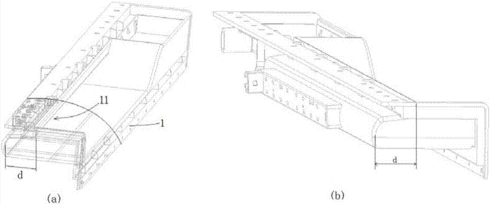
[0053] Such as Figure 5 As shown in , generally for the groove area that is difficult to be cured by the integral UV curing device, the space is relatively small. When the UV lamp 42 is inserted, the distance between the UV lamp 42 and the two side walls of the groove 11 is relatively close, and the UV While the lamp tube 42 is emitting light, it generates a large amount of heat energy, which is affected by strong light and heat, causing wrinkles in some areas, and new problems are prone to appear on the contrary. Through the shading plate 44 provided, the product can be protected in the limite...
PUM
 Abstract
Description
Claims
Application Information
 - R&D
- Intellectual Property
- Life Sciences
- Materials
- Tech Scout
- Unparalleled Data Quality
- Higher Quality Content
- 60% Fewer Hallucinations
Browse by: Latest US Patents, China's latest patents, Technical Efficacy Thesaurus, Application Domain, Technology Topic, Popular Technical Reports.
© 2025 PatSnap. All rights reserved.Legal|Privacy policy|Modern Slavery Act Transparency Statement|Sitemap|About US| Contact US: help@patsnap.com