Method and device for testing abrasive resistance of optical cable

A test equipment and wear resistance technology, applied in the direction of testing wear resistance, etc., can solve problems such as failure to protect or fix the optical cable well, damage to the structural stability of the optical cable, unstable transmission performance of the optical cable, etc. Economical, reliable and easy to operate

Pending Publication Date: 2017-10-10
江苏通光电子线缆股份有限公司
View PDF7 Cites 2 Cited by
  • Summary
  • Abstract
  • Description
  • Claims
  • Application Information

AI Technical Summary

Problems solved by technology

It will directly affect the use of the optical cable. If the wear resistance of the optical cable does not meet the requirements, the sheath of the optical cable will be broken due to mutual friction during the installation and use of the optical cable, and the internal structure of the optical cable cannot be well protected or fixed. The structural stability of the optical cable is destroyed, resulting in unstable transmission performance of the optical cable; at this time, when t

Method used


Image

  • Method and device for testing abrasive resistance of optical cable
  • Method and device for testing abrasive resistance of optical cable
  • Method and device for testing abrasive resistance of optical cable

Examples


Example Embodiment

[0024] Embodiment one

[0025] A single-core optical cable with a sheath with a nominal diameter of 1.8mm requires an abrasion resistance cycle of 1,000,000 times between optical cables, a speed of 10 times / second, and a hanging weight of 1.0kg.

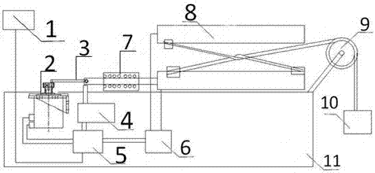
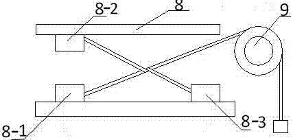
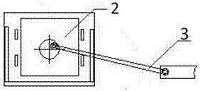
[0026] like figure 1 The equipment shown is tested by first attaching a section of fiber optic cable to the figure 2 Use the two lower clamps to fix it, and then fix one end of the other optical cable with the upper clamp, connect the other end with a 1.0kg weight, wrap around the lower fixed optical cable and place it on the fixed pulley. The placed optical cable sample should be and figure 2 unanimous.

[0027] The equipment starts, enters the operation screen 10 of the man-machine interface, and the state of the motor of the private server is set to run. Enter the parameter setting, set the speed to 10 times per second, set the disconnection function to non-stop when disconnected, set the number of actions to 1,000,000 times...

Example Embodiment

[0028] Embodiment two

[0029] A kind of secondary buffer layer 62.5 / 125μm multimode optical fiber cable, the diameter of the optical cable is 0.9mm, the abrasion resistance cycle between optical cables is required to be 10000 times, the speed is 10 times / second, the hanging weight is 2.2N, and it is fixed around the bottom Place the optical cable on the fixed pulley after one lap, and the placed optical cable sample should be the same as figure 2 unanimous.

[0030] like figure 1 The equipment shown is tested by first attaching a section of fiber optic cable to the figure 2Use the two lower clamps to fix it, and then fix one end of the other optical cable with the upper clamp, and connect the other end to a 2.2N weight, and place it on the fixed pulley after wrapping around the lower fixed optical cable. The placed optical cable sample should be and figure 2 unanimous.

[0031] The equipment starts, enters the operation screen 10 of the man-machine interface, and the ...


PUM

PropertyMeasurementUnit
Diameteraaaaaaaaaa
Diameteraaaaaaaaaa
Diameteraaaaaaaaaa

Abstract

The invention discloses a device for testing abrasive resistance of an optical cable. The device comprises a clamp device, a crankshaft connecting rod mechanism, a needle bearing, a human-computer interface operation screen and an electric cabinet; the device is characterized in that the clamp device comprises a clamp I, a clamp II, a clamp III and a fixed guide wheel; the clamp I, the clamp II and the clamp III are respectively arranged along upper, lower and left directions of the clamp device; the fixed guide wheel is located above the electric cabinet; the clamp device is arranged above the electric cabinet; the electric cabinet comprises a servo motor, a counter, a PLC (Programmable Logic Controller) and a conducting control switch; the counter is arranged on the crankshaft connecting rod mechanism; the crankshaft connecting rod mechanism is arranged between the servo motor and the clamp device; the servo motor is connected with the PLC; the PLC is connected with the human-computer interface operation screen; the human-computer interface operation screen is arranged above the exterior of the electric cabinet. The device can keep long-term stable running, is not changed following the change of the external environment factors, such as temperature and humidity, is characterized by being convenient in operation, high in precision, and long in service life and is economical and reliable.

Description

technical field [0001] The invention relates to the testing technology of optical cables, in particular to a method and equipment for testing the abrasion resistance between optical cables. Background technique [0002] The processing purpose of the optical cable is to protect the optical fiber inside, so that the optical fiber can be used normally under certain environmental conditions or mechanical stress. The performance test of optical cable is very important to the quality of optical cable products. It will directly affect the use of the optical cable. If the wear resistance of the optical cable does not meet the requirements, the sheath of the optical cable will be broken due to mutual friction during the installation and use of the optical cable, and the internal structure of the optical cable cannot be well protected or fixed. The structural stability of the optical cable is destroyed, resulting in unstable transmission performance of the optical cable; at this time...

Claims


Application Information

Patent Timeline
IPC IPC(8): G01N3/56
CPCG01N3/56
Inventor 单海龙陈辉彭晓鹏丁春风张仁杰
Owner 江苏通光电子线缆股份有限公司
Why Eureka
Try Eureka