Micro-current measuring circuit for dielectric response test

A technology for measuring circuit and dielectric response, applied in the direction of only measuring current, measuring electrical variables, measuring current/voltage, etc. Radiation and high-frequency radiation interference, inability to measure current signals in the frequency range, etc., to achieve the effect of not easy to be affected by external temperature, suppress power frequency and radiation interference, and have high test stability

Active Publication Date: 2017-10-10
STATE GRID HENAN ELECTRIC POWER ELECTRIC POWER SCI RES INST +2
View PDF11 Cites 11 Cited by
  • Summary
  • Abstract
  • Description
  • Claims
  • Application Information

AI Technical Summary

Problems solved by technology

But its disadvantage is: but because the feedback resistor with large resistance is required for current-voltage conversion, its output voltage signal will be interfered by power frequency radiation and high frequency radiation
The above two requirements indicate that the existing current amplification circuit or current testing method cannot well meet the actual needs
[0005] At the same time, another current measurement method based on Rogowski coils cannot measure current signals with higher or lower frequency ranges
This measurement method has a high isolation voltage, but it can only measure power frequency signals

Method used


Image

  • Micro-current measuring circuit for dielectric response test
  • Micro-current measuring circuit for dielectric response test

Examples


Embodiment 1

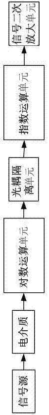
[0019] A microcurrent measurement circuit for dielectric response testing, comprising a logarithmic operation unit, a linear optocoupler unit, an exponential operation unit, and a signal secondary amplification unit, the logarithmic operation unit, a linear optocoupler unit, and an exponential operation unit and the signal secondary amplification unit are connected successively.

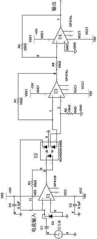
[0020] The logarithmic operation unit includes an amplifier with an ultra-low bias current and a negative feedback element, the linear optocoupler unit includes a linear optocoupler chip and a negative feedback circuit, and the exponential operation unit includes a high-speed operational amplifier and a photosensitive diode.

Embodiment 2

[0022] A microcurrent measurement circuit for dielectric response testing, comprising a logarithmic operation unit, a linear optocoupler unit, an exponential operation unit, and a signal secondary amplification unit, the logarithmic operation unit, a linear optocoupler unit, and an exponential operation unit and the signal secondary amplification unit are connected successively.

[0023] The logarithmic operation unit includes an amplifier with an ultra-low bias current and a negative feedback element, the linear optocoupler unit includes a linear optocoupler chip and a negative feedback circuit, and the exponential operation unit includes a high-speed operational amplifier and a photosensitive diode.

[0024] The amplifier with ultra-low bias current is OPA128.

Embodiment 3

[0026] A microcurrent measurement circuit for dielectric response testing, comprising a logarithmic operation unit, a linear optocoupler unit, an exponential operation unit, and a signal secondary amplification unit, the logarithmic operation unit, a linear optocoupler unit, and an exponential operation unit and the signal secondary amplification unit are connected successively.

[0027] The logarithmic operation unit includes an amplifier with an ultra-low bias current and a negative feedback element, the linear optocoupler unit includes a linear optocoupler chip and a negative feedback circuit, and the exponential operation unit includes a high-speed operational amplifier and a photosensitive diode.

[0028] The ultra-low bias current amplifier is OPA128.

[0029] The model of the linear optocoupler chip is HCNR201.


PUM


Abstract

The invention discloses a micro-current measuring circuit for dielectric response tests; the micro-current measuring circuit comprises a logarithm operation unit, a linear optical coupler unit, an index operation unit, and a signal secondary amplification unit connected in sequence; the logarithm operation unit comprises an ultra low bias current amplifier and a negative feedback element; the linear optical coupler unit comprises a linear optical coupler chip and a negative feedback circuit; the index operation unit comprises a high speed operation amplifier and a photosensitive diode; the micro-current measuring circuit has no feedback resistor, so the measuring result cannot be affected by a resistance temperature coefficient, thus providing high temperature drift influence inhibition ability, and the temperature coefficient can reach 100ppm/C.

Description

technical field [0001] The invention relates to the technical field of dielectric response testing of high-voltage electrical equipment, in particular to a microcurrent measurement circuit for dielectric response testing. Background technique [0002] In the field of dielectric response testing and high-voltage industrial applications, micro-current amplifier circuits are often used, and current amplifiers are required to have high precision. Currently on the market, I-V conversion amplifiers or sampling resistors are often used to amplify weak currents. [0003] For example, an I-V second-order differential measurement method and device disclosed in CN102323486A. The device includes a DC signal source, a function generator, an AC-DC adder with a voltage dividing function, a preamplifier, a lock-in amplifier and an environmental condition control system; The DC bias voltage superimposes and acts on the test sample together. The signal containing the test sample information...

Claims


Application Information

Patent Timeline
Patent Type & Authority Applications(China)
IPC IPC(8): G01R19/00
CPCG01R19/0092
Inventor 郑含博张大宁寇晓适李予全邵颖彪杨涛钱诗林
Owner STATE GRID HENAN ELECTRIC POWER ELECTRIC POWER SCI RES INST
Why Eureka
Try Eureka