
Method and device for removing dioxin from high-temperature flue gas

A high-temperature flue gas and dioxin technology, which is applied in combustion methods, combined devices, separation methods, etc., can solve the problems of small processing gas volume, regular replacement, environmental hazards, etc., to improve adsorption and decomposition efficiency, improve service life, The effect of reducing the amount of production

Inactive Publication Date: 2017-10-20
UNIV OF SCI & TECH BEIJING
View PDF19 Cites 13 Cited by
  • Summary
  • Abstract
  • Description
  • Claims
  • Application Information

AI Technical Summary

Problems solved by technology

For example, high-temperature pyrolysis is used to process dioxins. This method not only requires high equipment, but also requires high energy consumption during the treatment process, which increases the cost, and the processing capacity is limited, making it difficult to realize industrial applications; The inhibitors added usually bring some new pollution; the use of adsorbents to adsorb dioxins only transfers dioxins and usually needs to be used in conjunction with operations such as dust removal and washing, and the adsorption of dioxins The catalyst needs to be reprocessed, and the operation cost is high; if the catalytic decomposition of dioxin technology is adopted, there will be problems such as huge facility scale, catalyst poisoning and regular replacement, flue gas needs to be reheated, and the gas volume for treatment is small; no flue gas Quenching and only using ozone or ultraviolet rays to decompose dioxins cannot meet the emission standards
In addition, the above-mentioned technologies will produce fly ash containing high concentrations of dioxins during the treatment process, which is very harmful to the environment and must be disposed of as hazardous solid waste

Method used


Image

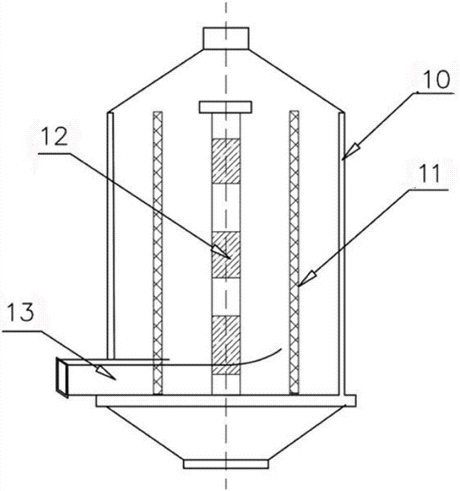
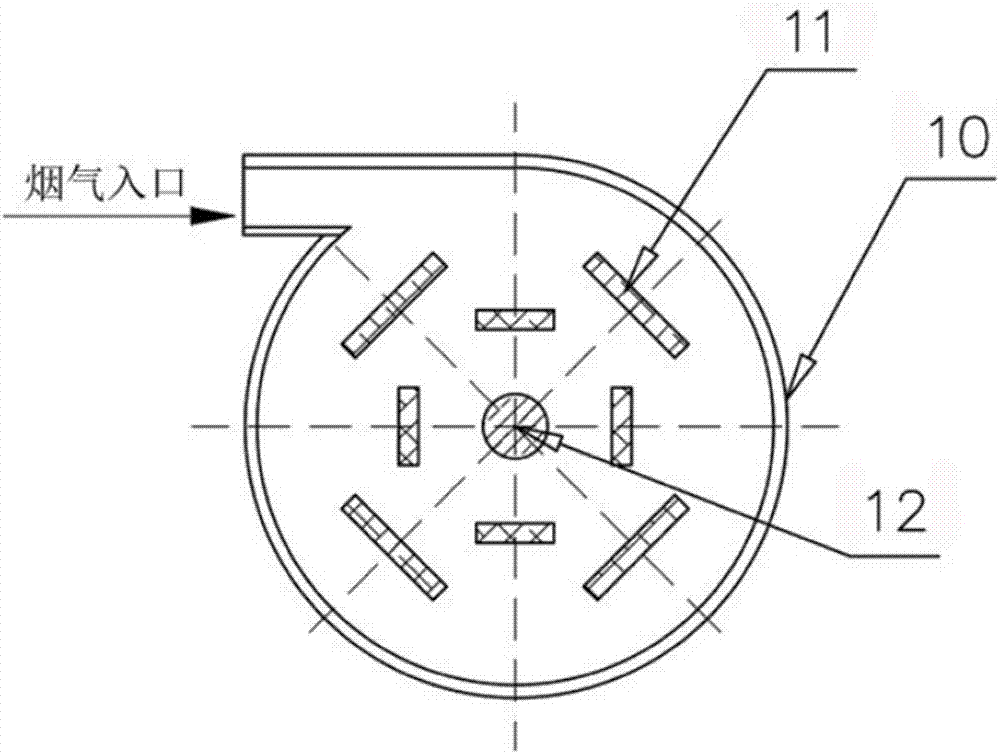
  • Method and device for removing dioxin from high-temperature flue gas
  • Method and device for removing dioxin from high-temperature flue gas
  • Method and device for removing dioxin from high-temperature flue gas

Examples


Embodiment 1

[0048] Firstly, waste heat is recovered from the high-temperature flue gas at 1400°C to reduce the temperature to 850°C; then the flue gas passes through a ceramic filter arranged in the flue to filter out particles above 30 μm, and then passes through a high-frequency filter with a working voltage of 80kV Dust removal by high-voltage electrostatic precipitator, the dust concentration is reduced to 20mg / m 3 Below; the flue gas after electrostatic precipitating is passed into the semi-dry reaction tower, and at a temperature of 750 ° C, 1.2 times the stoichiometric lime emulsion is sprayed to remove the acid gas in the flue gas; the flue gas after deacidification is quickly cooled to 120°C; the cooled flue gas passes through the bag filter for secondary dust removal, and the dust concentration is reduced to 10mg / m 3 Below; finally the flue gas is passed into the photolysis purification tower, and the toxic and harmful gases such as dioxin in the flue gas are adsorbed by the zeo...

Embodiment 2

[0050] First, waste heat is recovered from the high-temperature flue gas at 1350°C to reduce the temperature to 820°C; then the flue gas passes through a ceramic filter arranged in the flue to filter out particles above 30 μm, and then passes through two high-frequency generators with a working voltage of 60kV Dust removal by high-voltage electrostatic precipitator, the dust concentration is reduced to 20mg / m 3 Below; the flue gas after electrostatic precipitator is passed into the semi-dry reaction tower, and at 720 ° C, spray 1.5 times the stoichiometric sodium carbonate solution to remove the acid gas in the flue gas; the flue gas after deacidification is rapidly cooled to 140°C; the cooled flue gas is dusted twice by the bag filter, and the dust concentration is reduced to 10mg / m 3 Below; finally the flue gas is passed into the photolysis purification tower, the toxic and harmful gases such as dioxin in the flue gas are adsorbed by the activated carbon adsorbent, and are c...

Embodiment 3

[0052] First, waste heat is recovered from the high-temperature flue gas at 1300°C to reduce the temperature to 800°C; then the flue gas passes through a ceramic filter arranged in the flue to filter out particles above 30 μm, and then passes through two high-frequency generators with a working voltage of 70kV Dust removal by high-voltage electrostatic precipitator, the dust concentration is reduced to 20mg / m 3 Below; the flue gas after electrostatic precipitating is passed into the semi-dry reaction tower, and at a temperature of 650 ° C, 1.2 times the stoichiometric sodium hydroxide solution is sprayed to remove the acid gas in the flue gas; the flue gas after deacidification is rapidly The temperature is lowered to 160°C; the flue gas after cooling is dedusted by the bag filter for the second time, and the dust concentration is reduced to 10mg / m 3 Below; finally the flue gas passes into the photolysis purification tower, the toxic and harmful gases such as dioxin in the flu...


PUM


Abstract

The invention mainly belongs to the technical field of a treating method for high temperature flue gas and a device thereof and specifically relates to a method and a device for removing dioxin from high-temperature flue gas. The method comprises the following steps: firstly, recycling the waste heat of the high-temperature flue gas, removing dust and de-acidifying and then quickly cooling, removing the dust for the second time, entering into a photo-decomposing purifying tower for decomposing dioxin and then emitting. The resynthesis of dioxin is restrained in the manner of recycling the waste heat of the high-temperature flue gas, removing dust and de-acidifying and then quickly cooling and the ultraviolet ray is utilized to catalytically decompose dioxin, so that the simple and efficient removal of the dioxin in the high-temperature flue gas is realized. The method and the device for removing the dioxin according to the invention have the characteristics of simplicity, high efficiency, and the like, and are easy for industrial application.

Description

technical field [0001] The invention mainly belongs to the technical field of high-temperature flue gas treatment methods and devices thereof, and in particular relates to a method and device for removing dioxins in high-temperature flue gas. Background technique [0002] Dioxin is a class of tricyclic aromatic organic compounds composed of 2 or 1 oxygen atom connected to 2 benzene rings substituted by chlorine. Due to the difference in the number and position of chlorine atoms, a total of There are 75 isomers of polychlorinated dibenzodioxins (PCDDs) and 135 isomers of polychlorinated dibenzofurans (PCDFs). Dioxins are lipophilic and chemically stable, and they begin to decompose at temperatures above 700°C. They are easy to deposit in soil and organisms, and accumulate in large quantities in the human body through the food chain. Dioxin is a highly toxic and harmful substance, which has carcinogenicity, teratogenicity, and immunotoxicity to humans. Its toxicity is equival...

Claims


Application Information

Patent Timeline
IPC IPC(8): B01D53/75B01D53/40B01D53/72B01D50/00F23G5/46F23J15/02F27D17/00
CPCB01D50/00B01D53/40B01D53/72B01D53/75B01D2258/0283B01D2259/804F23G5/46F23J15/025F27D17/004F27D2017/005Y02P10/25
Inventor 张深根刘波杨强威范文迪
Owner UNIV OF SCI & TECH BEIJING
Learn More