Automatic laser welding device with CCD vision detection function and welding method

A laser welding and laser technology, applied in the field of automatic laser welding equipment, can solve the problems of low efficiency, poor welding quality, poor positioning effect of welding head, etc., and achieve the effect of easy adjustment of positioning, improvement of welding efficiency, and improvement of positioning accuracy

Active Publication Date: 2017-10-20
SHANGHAI WINKELMANN LONGCHUAN (SWL) MOTORCOMPONENTS CO LTD
View PDF6 Cites 12 Cited by
  • Summary
  • Abstract
  • Description
  • Claims
  • Application Information

AI Technical Summary

Problems solved by technology

[0003] The purpose of the present invention is to overcome the above-mentioned prior art welding equipment mentioned bulky, poor welding head positioning effect, poor welding quality, low efficiency and other problems

Method used


Image

  • Automatic laser welding device with CCD vision detection function and welding method
  • Automatic laser welding device with CCD vision detection function and welding method
  • Automatic laser welding device with CCD vision detection function and welding method

Examples


Embodiment 1

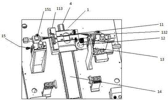
[0030] The product 111 fixture 11 is arranged on the feeding shaft 14, and its function is to fix and clamp the product 111 to be welded, and the feeding method is manual loading and unloading directly.

[0031] The rotary compression cylinder 112 is used to compress the product 111 to be welded after the loading of the product 111 to be welded is completed, so as to reduce the impact of the vibration caused during the movement on the welding machine.

[0032] The positioning datum 113 with guide rail is used to keep the positioning of the left side of the product to be welded relatively consistent each time the material is loaded.

[0033] The function of the feeding shaft 14 is to transport the product 111 fixture 11 to the position of the industrial camera 12 at a stable and uniform speed to take pictures and deliver the photographed information to the industrial control system 3 for calculation and processing. After completion, the product 111 is further sent to the four-di...


PUM


Abstract

The invention discloses an automatic laser welding device with a CCD vision detection function and a welding method. The device comprises a laser device and a rack cover and further comprises a feeding device provided with a guide rail positioning benchmark, a clamp, a feeding shaft and a rotary pressing air cylinder and horizontally arranged on the laser platform, a two-dimensional laser arranged at one end of the laser platform and provided with a first laser head, a four-dimensional laser arranged at the other end of the laser platform and provided with a second laser head and a CCD vision positioning camera, and a PC controller arranged in the rack cover. The automatic laser welding device has the beneficial effects that the device obtains an image signal of a target through the CCD vision positioning camera, the PC controller calculates a corresponding target position and drives the device to conduct position positioning, the welding precision is improved due to use of machine vision and image processing, tool and product errors are avoided, and influences of human factors on product quality is avoided.

Description

technical field [0001] The invention relates to the fields of laser welding and automatic detection, in particular to an automatic laser welding device and a welding method with CCD detection. Background technique [0002] In recent years, laser welding has developed rapidly in the automotive industry. How to innovate and integrate equipment so that laser welding equipment and visual inspection devices can work together, improve automation, reduce equipment footprint, and save costs is the key to developing this system LLL. Welding equipment equipped with visual imaging detection devices is a relatively new idea. The traditional welding method lacks visual imaging equipment and corresponding control software. Few have automatic capture of product welding seam position and calculate welding torch offset distance to realize automatic welding products, and few have four-dimensional laser welding head, welding position error is large, welding quality is poor, and efficiency is...

Claims


Application Information

Patent Timeline
Patent Type & Authority Applications(China)
IPC IPC(8): B23K26/21B23K26/03B23K26/70
CPCB23K26/032B23K26/21B23K26/702
Inventor 肖松王利融
Owner SHANGHAI WINKELMANN LONGCHUAN (SWL) MOTORCOMPONENTS CO LTD
Why Eureka
Try Eureka