Portable aviation cable fault test system

A technology of cable fault and testing system, which is applied in the direction of fault location, fault detection according to conductor type, fault detection by pulse reflection method, etc. It can solve the problems of difficult environmental noise, inconvenient communication, slow test speed, etc., and achieve the reduction of wrong disassembly The number of times, avoiding the reduction of cable life, and the effect of fast and accurate positioning

Pending Publication Date: 2017-10-24
崔旭涛
View PDF12 Cites 19 Cited by
  • Summary
  • Abstract
  • Description
  • Claims
  • Application Information

AI Technical Summary

Problems solved by technology

The current practice is usually to use an ordinary digital multimeter, connect a very long wire, and test each terminal point at both ends of the cable by two testers. This method has many inconveniences:
[0004] 1) The distance between the two ends of the tested cable is likely to be far away, and it is very inconvenient to pull a long wire during the test;
[0005] 2) Two people must cooperate during the test, and they must communicate and coordinate with each other. The long distance makes communication inconvenient, especially when the ambient noise is high;
[0006] 3) Many of the tested cable heads are in a relatively dark and narrow space, and the testers "drill" to find small cable nodes in it, which is inaccurate and easy to fatigue;
[0007] 4) It needs to be tested point by point, and each point needs to be determined by two people, so the test speed is very slow;
[0008] 5) The test items are not comprehensive, only the on-off test can be performed, and the failures such as on-resistance, insulation resistance, withstand voltage and pin shrinkage cannot be tested

Method used


Image

  • Portable aviation cable fault test system
  • Portable aviation cable fault test system
  • Portable aviation cable fault test system

Examples


Embodiment Construction

[0048] The principles and features of the present invention are described below in conjunction with the accompanying drawings, and the examples given are only used to explain the present invention, and are not intended to limit the scope of the present invention.

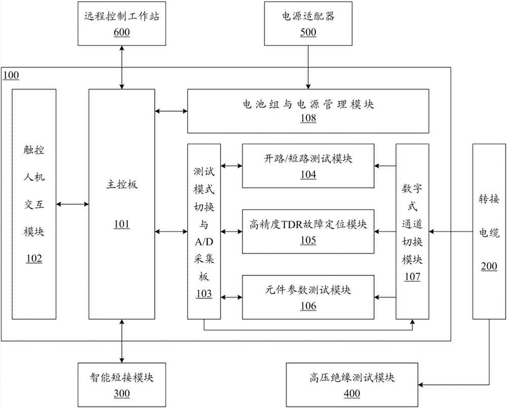
[0049] Please refer to figure 1As shown, it is a schematic structural diagram of the portable aviation cable fault testing system of the present invention. The test system includes: a host 100, an adapter cable 200, an intelligent short-circuit module 300, a high-voltage insulation test module 400, a power adapter 500, and a remote control workstation 600; the adapter cable 200, the intelligent short-circuit module 300, Both the power adapter 500 and the remote control workstation 600 are connected to the host 100, and the high voltage insulation test module 400 is connected to the adapter cable 200; wherein,

[0050] The host 100 is equipped with: a main control board 101, a touch human-computer interaction module...


PUM


Abstract

The invention discloses a portable aviation cable fault test system comprising a host and an adapter cable, an intelligent shorting module and a remote control work station which are connected with the host. The host is provided with a main control panel, a touch control human-computer interaction module, a test mode switching and A/D acquisition board, an open circuit/short circuit test module, a high-precision TDR fault locating module, an element parameter test module and a digital channel switching module. The main control panel receives the operation instruction of the user and the remote control work station to control all the modules to perform measurement operation. The human-computer interaction module and the test mode switching and A/D acquisition board are connected with the main control panel. The open circuit/short circuit test module, the fault locating module and the element parameter test module are connected with the test mode switching and A/D acquisition board. The channel switching module is connected with the open circuit/short circuit test module, the fault locating module and the element parameter test module. The adapter cable is connected with the digital channel switching module of the host.

Description

technical field [0001] The invention relates to the field of cable testing, in particular to a portable aviation cable fault testing system. Background technique [0002] The aviation cable is the nervous system of the aircraft, which transmits power supply, transmits control signals and data information to the aircraft's electrical, avionics, communication, control and other systems. In aircraft maintenance, accurate detection of aviation cable faults is of great significance to ensure aircraft quality and flight safety. [0003] The feedback information from the survey shows that during the assembly and commissioning of various aircraft (such as helicopters, fighter jets, etc.) and the use and maintenance of troops, there will be problems with the need to test the cables on the aircraft due to the abnormal operation of the airborne equipment. The current practice is usually to use an ordinary digital multimeter, connect a very long wire, and test each terminal point at bo...

Claims


Application Information

Patent Timeline
Patent Type & Authority Applications(China)
IPC IPC(8): G01R31/08G01R31/11
CPCG01R31/083G01R31/11
Inventor 崔旭涛赵红军孙佳星王威王磊王鲁彬
Owner 崔旭涛
Why Eureka
Try Eureka