Quantitative phase micro-imaging method based on annular programmable LED lighting

A technology of LED illumination and phase microscopy, applied in microscopes, instruments, optics, etc., can solve the problems of limiting the spatial resolution and measurement accuracy of the imaging system, unable to collect useful signals, and complexity, to improve compatibility and flexibility. The effect of improving the utilization rate of light energy

Active Publication Date: 2017-10-24
NANJING UNIV OF SCI & TECH
View PDF5 Cites 22 Cited by
  • Summary
  • Abstract
  • Description
  • Claims
  • Application Information

AI Technical Summary

Problems solved by technology

However, the interferometry method has obvious disadvantages: (1) interferometry generally requires a highly coherent light source (such as a laser), which requires a more complex interferometric device; (2) the introduction of an additional reference optical path leads to requirements for the measurement environment (3) Speckle coherent noise introduced by highly coherent light sources limits the spatial resolution and measurement accuracy of the imaging system
Here there is the selection of imaging resolution and image measurable contrast. The contrast of the image is the strongest under the condition of coherent illumination, but the imaging resolution at this time is only determined by the numerical aperture of the objective lens.
When t

Method used


Image

  • Quantitative phase micro-imaging method based on annular programmable LED lighting
  • Quantitative phase micro-imaging method based on annular programmable LED lighting
  • Quantitative phase micro-imaging method based on annular programmable LED lighting

Examples


Example Embodiment

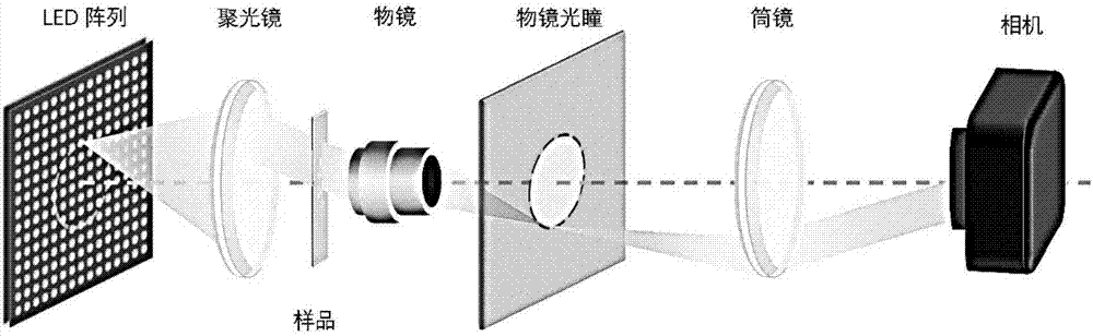
[0020] like figure 2As shown, the present invention is a high-efficiency quantitative phase microscopy imaging system based on annular programmable LED illumination. The actual hardware platform of the imaging system includes an LED array, a stage, a condenser, a sample to be tested, a microscope objective lens, and an imaging tube. Mirror, camera, the system uses a ring-shaped illumination pattern and adds a condenser lens to the light path. The LED array is placed at the front focal plane of the condenser, and the center of the LED array is on the optical axis of the microscope objective, the back focal plane of the microscope objective coincides with the front focal plane of the imaging tube lens, and the imaging plane of the camera is placed in the imaging The position of the back focal plane of the tube lens; during imaging, the sample to be tested on the stage is adjusted to the position of the front focal plane of the microscope objective lens to form an infinity-corre...


PUM


Abstract

The invention discloses an efficient quantitative phase micro-imaging method based on annular programmable LED lighting. The method comprises the following steps that: system optical transfer function derivation under a partial coherent lighting imaging system is performed; phase transfer function derivation under weak object approximation is performed under inclination axis symmetric coherent point light source lighting; extension from an optical axis symmetric coherent point light source to a discrete annular point light source is performed, and incoherent superposition of the system transfer function under the condition of optical axis symmetry is performed; original image acquisition is performed; and quantitative phase deconvolution reconstruction is performed. The system phase transfer function of the inclination axis symmetric point light source under the condition of partial coherent lighting is derived and popularized and applied to the optical transfer function of the discrete annular point light source; and the annular lighting aperture is enabled to be flexible and adjustable by the programmable control mode of the LED array so as to be suitable for the microscope objective of different numerical aperture and enhance the compatibility and flexibility of the system.

Description

technical field [0001] The invention belongs to optical microscopic measurement and imaging technology, in particular to a high-efficiency quantitative phase microscopic imaging method based on annular programmable LED illumination. Background technique [0002] Phase recovery is an important technology in optical measurement and imaging, and plays an important role in both biomedical and industrial inspection. The most classic quantitative phase measurement method is interferometry (Cuche E, Bevilacqua F, Depeursinge C. Digital holography for quantitative phase-contrast imaging[J]. Opticsletters, 1999, 24(5): 291-293.) The beam produces two beams of light. The object light passes through the sample and then interferes with the reference light, resulting in interference fringes. The phase delay of the object can be obtained through the demodulation algorithm. However, the interferometry method has particularly obvious disadvantages: (1) interferometry generally requires a h...

Claims


Application Information

Patent Timeline
IPC IPC(8): G02B21/06G02B21/36
CPCG02B21/06G02B21/365G02B21/14G02B21/008G02B21/361G02B21/0056
Inventor 陈钱李加基左超孙佳嵩张佳琳顾国华张玉珍范瑶冯世杰陶天阳胡岩张良
Owner NANJING UNIV OF SCI & TECH
Why Eureka
Try Eureka