Gap waveguide series feed high-gain millimeter wave antenna

A millimeter-wave antenna and gap waveguide technology, which is applied to antenna arrays, slot antennas, antennas and other directions that are energized separately, can solve problems such as low front efficiency and complex structure, achieve high gain, improve aperture efficiency, and achieve large-scale production effect

Inactive Publication Date: 2017-10-24
NANJING UNIV OF SCI & TECH
View PDF5 Cites 19 Cited by
  • Summary
  • Abstract
  • Description
  • Claims
  • Application Information

AI Technical Summary

Problems solved by technology

In the prior art, the two-dimensional high-gain two-dimensional array is generally realized by using the gap

Method used


Image

  • Gap waveguide series feed high-gain millimeter wave antenna
  • Gap waveguide series feed high-gain millimeter wave antenna
  • Gap waveguide series feed high-gain millimeter wave antenna

Examples


Embodiment 1

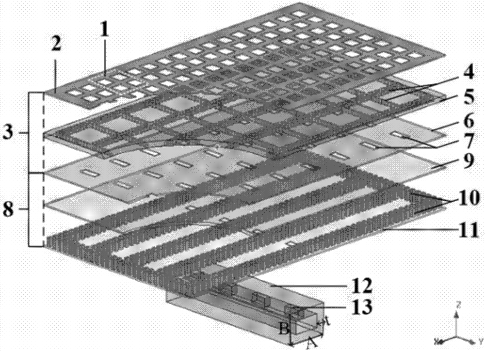
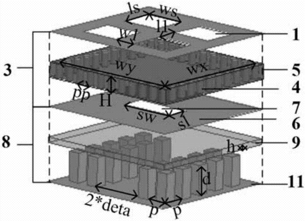
[0036] The overall antenna size is 38.4mm*22mm*7.108mm.

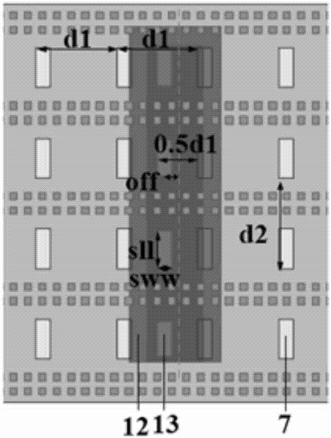
[0037] combine figure 1 , 2 , 3, 7, according to the structure discussed in the specific embodiment, through electromagnetic simulation software HFSS modeling and simulation, the relevant dimensions of the antenna are set as follows (unit: millimeter):

[0038] ws=1.6mm, ls=1.4mm, w1=0.8mm, l1=0.8mm, wx=4.5mm, wy=4.5mm, sw=0.8mm, sl=2.2mm, deta=1.9mm, off=0.6mm, a=0.4mm, sll=1.98mm, sww=0.8mm, p=0.8mm, d=1.0mm, h=0.2mm, d1=4.5mm, d2=5.0mm, H=0.508mm, dd=0.25mm, pp=0.45mm, A=5.1mm, B=3.55mm, t=1mm.

[0039] combine Figure 4 , the reflection coefficient |S11| of the millimeter-wave antenna array sub-array fed by slot-shaped gap waveguides in series in the present invention is less than -10dB from 74.6GHz to 85GHz, the gain variation within this frequency band is less than 1dB, and the sub-array gain is over 90%.

[0040] combine Figure 5 The working frequency band of the millimeter-wave antenna array fed by slot-s...


PUM


Abstract

The invention discloses a gap waveguide series feed high-gain millimeter wave antenna, and the antenna comprises a high-efficiency radiation unit subarray layer, a gap waveguide slot-coupling series feed network and a waveguide slot-coupling feed structure. The high-efficiency radiation unit subarray layer comprises a rectangular metal medium resonant cavity and a metal layer which is disposed on the upper surface of the rectangular metal medium resonant cavity in a coated manner and is provided with four rectangular slots. A wide side of a rectangular waveguide is provided with a coupling slot, so as to achieve the feed of the center of each gap waveguide. The plurality of gap waveguides are laterally arranged in an aligned manner to form a two-dimensional feed network. The wide side of each gap waveguide is provided with a coupling slot, so as to achieve the feed of each corresponding radiation subarray of the upper layer. The subarrays are excited to radiate energy to a space. The antenna provided by the invention works at the millimeter wave frequency band nearby 77GHz, is high in efficiency, is good in radiation characteristics, is low in cost, is easy to machine, is small in size, is high in stability, and is suitable for batch production.

Description

technical field [0001] The invention relates to a millimeter-wave antenna technology, in particular to a millimeter-wave array antenna based on slot-shaped gap waveguide series feeding. Background technique [0002] For the millimeter wave band, especially the frequency band above 60 GHz, the traditional microstrip line and coplanar waveguide and other planar transmission lines will have high transmission loss due to dispersion and loss of dielectric materials, and due to size limitations, the processing accuracy The requirements are extremely high; on the other hand, rectangular waveguides and coaxial transmission lines are used due to their low loss at high frequencies, but in the millimeter wave band there are still problems of complex processing technology, high cost, and difficulty in integrating with active microwave electronic circuits. [0003] Literature 1 (P.S.Kildal, E.Alfonso, A.Valero-Nogueira and E.Rajo-Iglesias, "Local Metamaterial-Based Waveguides in Gaps Bet...

Claims


Application Information

Patent Timeline
IPC IPC(8): H01Q1/38H01Q21/06H01Q13/10H01Q1/50H01Q1/48
CPCH01Q1/38H01Q1/48H01Q1/50H01Q13/10H01Q21/061
Inventor 王昊季爽曹建银郑玉雪
Owner NANJING UNIV OF SCI & TECH
Why Eureka
Try Eureka