Sponge type permeable reactive barrier system

A osmotic reaction wall and sponge technology, applied in water/sludge/sewage treatment, water pollutants, biological water/sewage treatment, etc., can solve the problems of polluting groundwater, narrow use range, and difficult to deal with large-scale polluted water , to achieve the effect of reducing the concentration and improving the repairing effect

Pending Publication Date: 2017-11-03
NANCHANG UNIV
View PDF6 Cites 5 Cited by
  • Summary
  • Abstract
  • Description
  • Claims
  • Application Information

AI Technical Summary

Problems solved by technology

[0003] At present, there are mainly the following methods to deal with tailings leachate: 1. Physical shielding method, which uses the sealing method to enclose the polluted water and prevent it from spreading out. This method has a narrow range of application
2. Extraction treatment method, which is a method of pumping sewage out of the ground for treatment. This method has high investment costs and is difficult to treat large-scale polluted water
3. In-situ treatment method, which uses biology and permeable reaction wall (PRB) to treat underground polluted water. The input cost of the two methods is relatively low, and the bioremediation method is easily affected by the environment and is not conducive to treatment.
However, this technology is not effective in treating the high-concentration and large-flow leachate produced by heavy rain, especially in tailing mines. When the rain comes, the leachate is discharged in large quantities and contains high-concentration harmful substances. The leachate flow exceeds the load of the permeable reaction wall. Spills, spilled leachate can still contaminate groundwater

Method used


Image

  • Sponge type permeable reactive barrier system
  • Sponge type permeable reactive barrier system
  • Sponge type permeable reactive barrier system

Examples


Embodiment Construction

[0023] The present invention will be further described below in conjunction with the accompanying drawings and embodiments.

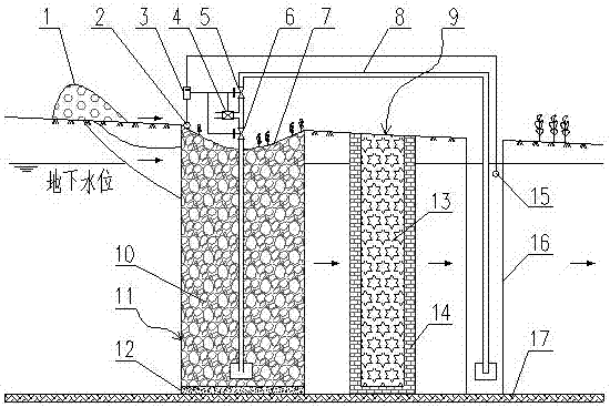
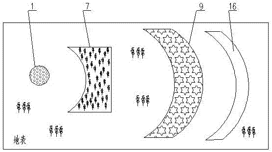
[0024] to combine figure 1 and figure 2 , a kind of sponge type permeable reaction wall system provided by the present invention, comprises sunken green belt 7, sponge reservoir 11, water pump 4, sensor I2, permeable reaction wall 9, detection belt 16, sensor II15, controller 3 .

[0025] The sunken green belt 7 is arranged downstream of the tailings 1, and the surface of the sunken green belt 7 is set in a concave shape, and a sensor I2 is set at the entrance.

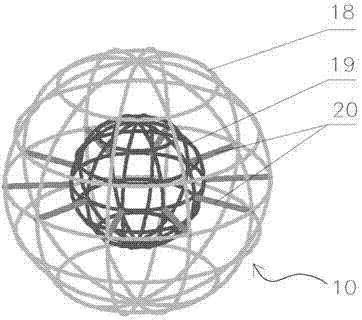
[0026] The sponge reservoir 11 is arranged directly below the sunken green belt 7, the interior of the sponge reservoir 11 is filled with hollow filler 10, and the sides and bottom are provided with anti-seepage layers 12 respectively.

[0027] The permeable reaction wall 9 is arranged downstream of the sponge reservoir 11 , the permeable reaction wall 9 includes a reaction medium 13 and a ...


PUM

PropertyMeasurementUnit
Elastic modulusaaaaaaaaaa

Abstract

The invention discloses a sponge type permeable reactive barrier system which is applied to treatment on tailing percolate pollution and comprises a sponge reservoir, a sunk green belt, a permeable reactive barrier, a detection zone and a water pump, wherein the sunk green belt is arranged at the downstream of tailings; the sponge reservoir is arranged right below the sunk green belt; the permeable reactive barrier is arranged at the downstream of the sponge reservoir. Due to adoption of the sponge reservoir at the downstream of the permeable reactive barrier, large-flow percolate can be stored and buffered, and the load of the percolate to the permeable reactive barrier is buffered; a water body inside the sponge reservoir is compulsively circulated through the water pump, and then sudden high-concentration harmful substance percolate can be diluted; by flowing back a water body of which the concentration exceeds standards inside the detection zone, the sewage treatment performance is improved. The sponge type permeable reactive barrier system is capable of effectively treating water body pollution such as tailing percolate and is low in operation maintenance cost and long in treatment action time.

Description

technical field [0001] The invention relates to the technical field of underground sewage treatment, in particular to a sponge-type permeable reaction wall treatment system for tailings leachate. Background technique [0002] my country is rich in mineral resources, but the ore composition is complex and there are few single mines. Ore needs to go through a series of sorting operations to obtain concentrates, resulting in low comprehensive utilization of minerals and serious waste of resources. The remaining components after sorting are discharged in the form of slurry to form tailings. Tailings contain a large amount of metal minerals and non-metallic minerals, which will undergo complex reactions under the action of rain, light, and microorganisms. The heavy metal ions contained in the tailings leachate will not only endanger the surrounding groundwater and surface water, but also affect the surrounding areas. Soil can also cause serious pollution. [0003] At present, t...

Claims


Application Information

Patent Timeline
IPC IPC(8): C02F1/62C02F9/14C02F101/20C02F103/06
CPCC02F1/00C02F1/62C02F3/32C02F2103/06C02F2103/001C02F2101/20
Inventor 吴代赦李建龙况琴黄庭黄珊
Owner NANCHANG UNIV
Why Eureka
Try Eureka