an air compressor

A technology of air compressors and cylinders, which is applied in the field of air compressors with vibration-reducing and waterproof functions. It can solve the problems of poor thermal conductivity of wear-resistant materials such as graphite, small spaces, large noise and vibration, and achieve waterproof and vibration-reducing stability. Reliable, improved heat dissipation efficiency, good thermal conductivity effect

Active Publication Date: 2020-06-05
浙江盛源空压机制造有限公司
View PDF6 Cites 2 Cited by
  • Summary
  • Abstract
  • Description
  • Claims
  • Application Information

AI Technical Summary

Problems solved by technology

[0002] At present, in the field of public transportation, the share of new energy vehicles is getting higher and higher. There are many pneumatic components inside new energy vehicles, so air compressors are needed to provide air sources. The current air compressors mainly include motors, boxes, cylinders and missing covers. and other components, the noise and vibration of the existing conventional air compressor are relatively large, and the waterproof performance level is low, which cannot meet the needs of new energy vehicles
[0003] The air compressor is installed inside the new energy vehicle, and the space is narrow. The heat dissipation performance of the air compressor is high, and the heat dissipation performance of the existing air compressor cannot meet the needs well.
[0004] In addition, the inner wall of the existing air compressor cylinder is coated with wear-resistant materials such as graphite, and the piston ring is generally made of polytetrafluoroethylene rings. When the air compressor is working, toxic gases will be produced. Because the ventilation is better in ordinary workshops, this trace amount of toxic gases The gas is not harmful to the human body, but the new energy vehicle in the sealed space will, a small amount of toxic gas enter the compartment with the air conditioning system, which is more harmful; at the same time, wear-resistant materials such as graphite have poor thermal conductivity and hinder the heat transfer layer. , the heat generated by the piston cannot be transferred to the cylinder in time, which will cause a large temperature difference between the inside and outside and affect the heat dissipation performance of the air machine

Method used


Image

  • an air compressor
  • an air compressor

Examples


Embodiment Construction

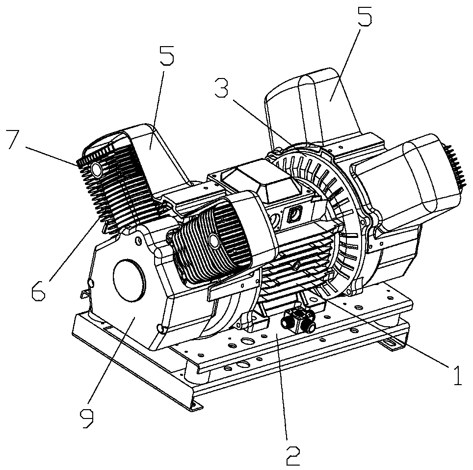
[0024] Such as Figure 1-6 As shown, an air compressor includes a motor 1, a casing 4, a cylinder 6, a valve plate, a cylinder head 7 and a base 2, the cylinder 6 is connected to the cylinder head 7, a valve plate is set between the cylinder 6 and the cylinder head 7, and the box A crank 41 is arranged in the body 4, and the crank 41 is connected to the output shaft of the motor 1. The output end of the crank 41 is connected to the piston device 51 inside the cylinder 6 through the connecting rod 42. It is characterized in that: the output shaft of the motor 1 A cooling fan device 3 coaxially arranged with the crank 41 is also connected to the top, and a wind guide cover 5 is arranged between the cooling fan device 3 and the cylinder and the cylinder head.

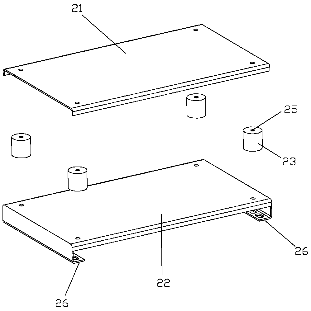
[0025] The base 2 includes an upper plate 21, a bottom plate 22 and a damping column 23, the upper plate 21 and the base plate 22 are parallel to each other, and are connected by a number of damping columns 23. The describ...


PUM


Abstract

The invention relates to an air compressor. Flaky heat dissipation fins are arranged on the surfaces of air cylinders and cylinder covers, and the output end of a motor is connected with a heat dissipation fan. Guide covers are arranged between the heat dissipation fan and the air cylinders and the cylinder covers. The output of the motor drives the fan to conduct heat dissipation on the air cylinders and the cylinder covers meanwhile pressurizing is conducted. According to the air compressor, the heat dissipation efficiency of the air compressor is greatly improved, the exhaust gas temperature can be effectively lowered, thus, the temperature of a piston and a piston ring is also lowered, and the life of the piston ring is prolonged; and in addition, waterproof and dustproof treatment is conducted on the motor, a box body, the air cylinders and the cylinder covers, so that the air compressor has a good waterproof and dustproof grade.

Description

technical field [0001] The invention and the air compressor technology specifically relate to an air compressor with a vibration damping and waterproof function. Background technique [0002] At present, in the field of public transportation, the share of new energy vehicles is getting higher and higher. There are many pneumatic components inside new energy vehicles, so air compressors are needed to provide air sources. The current air compressors mainly include motors, boxes, cylinders and missing covers. And other components, the noise and vibration of the existing conventional air compressor are relatively large, and the waterproof performance level is low, which cannot meet the needs of new energy vehicles. [0003] The air compressor is installed inside the new energy vehicle, the space is narrow, and the heat dissipation performance of the air compressor is high, and the heat dissipation performance of the existing air compressor cannot meet the needs well. [0004] I...

Claims


Application Information

Patent Timeline
Patent Type & Authority Patents(China)
IPC IPC(8): F04B35/04F04B39/00F04B39/06F04B39/12
CPCF04B35/04F04B39/00F04B39/0044F04B39/066F04B39/126
Inventor 朱家泉黄春水陈志杰
Owner 浙江盛源空压机制造有限公司
Why Eureka
Try Eureka