Method based on split ring resonators (SRRs) for improving impedance matching and expanding frequency band of annular antenna

A loop antenna and impedance matching technology, applied to loop antennas, antennas, electrical components, etc., can solve the problems of poor port matching, low efficiency, and low radiation resistance, and achieve the effect of low profile

Inactive Publication Date: 2017-11-03
HANGZHOU DIANZI UNIV
View PDF7 Cites 8 Cited by
  • Summary
  • Abstract
  • Description
  • Claims
  • Application Information

AI Technical Summary

Problems solved by technology

Small loop antennas have small radiation resistance and low efficiency, and are usually used for receiving antennas. Large loop antennas not only have extremely high radiation efficiency, but also have an input impedance close to pure resistance at the resonant frequency, which brings great convenience to the impedance matching of the antenna. Unfortunately, although the input impedance is similar to pure resistance, the resistance value is too high, usually between 100 and 150 ohms, which is poorly matched with the standard 50 ohm transmission line port. Difficult to meet actual needs

Method used


Image

  • Method based on split ring resonators (SRRs) for improving impedance matching and expanding frequency band of annular antenna
  • Method based on split ring resonators (SRRs) for improving impedance matching and expanding frequency band of annular antenna
  • Method based on split ring resonators (SRRs) for improving impedance matching and expanding frequency band of annular antenna

Examples


Embodiment Construction

[0020] The present invention will be further described below in conjunction with accompanying drawing.

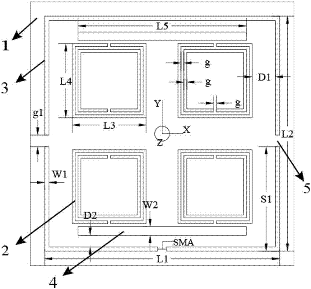
[0021] Such as figure 1 As shown, the novel loop antenna of the present invention includes a dielectric substrate (1), split resonator rings (SRRs) (2), loop antenna (3), and metal lines (4); the loop antenna is printed on the front part of the dielectric substrate, and the A loop opening (5) is opened at the position where the current phase is opposite on the loop, four equal-sized and symmetrical SRRs (2) are built in the antenna loop, and two symmetrical metal strips (4) are placed between the opening of the SRRs and the loop.

[0022] The inner and outer conductors of the SMA RF connector are respectively connected to both ends of the outer ring feeder port.

[0023] The antenna design of the present invention is carried out in the three-dimensional electromagnetic simulation software CST microwave studio, and the relevant dimensions are finally determined by parameter...


PUM


Abstract

The invention discloses a method based on split ring resonators (SRRs) for improving impedance matching and expanding frequency band of an annular antenna. The method involves a dielectric substrate, the SRRs, the annular antenna and metal strips, wherein the annular antenna is printed on a part of a region of a front surface of the dielectric substrate, in openings of a loop, the SRRs with appropriate sizes are arranged in an antenna ring, and the metal strips are arranged in the openings of SRRs. The openings in the ring and the built-in SRRs are used for improving impedance matching and expanding frequency points, the impedance bandwidth is expanded by placing the metal strips, and the impedance matching of the annular antenna and the frequency band expansion are perfectly achieved.

Description

technical field [0001] The invention belongs to the technical field of wireless communication, and relates to a method for improving impedance matching of a LOOP antenna (that is, a loop antenna) and extending a frequency band based on SRRs. Background technique [0002] The antenna is the "eye" of the wireless communication system, and it is responsible for the important task of transmitting and receiving electromagnetic signals. The rapid development of wireless communication makes the requirements for the antenna of the entire communication system continue to increase, so the research on the antenna is an important topic. Among them, the loop antenna is a basic antenna with a simple structure and low cost. Therefore, there are countless researches and developments based on the loop antenna, which are widely used in various communication systems, and people's exploration of the loop antenna has never stopped. [0003] Loop antennas are usually divided into rectangles, tria...

Claims


Application Information

Patent Timeline
Patent Type & Authority Applications(China)
IPC IPC(8): H01Q7/00
CPCH01Q7/00
Inventor 徐魁文刘洋赵文生陈世昌赵鹏王高峰
Owner HANGZHOU DIANZI UNIV
Why Eureka
Try Eureka