Ring surface worm gear hob CAD/CAM method based on general CNC milling machine

A worm gear hob, CNC milling machine technology, applied in the direction of geometric CAD, milling machine equipment, milling machine equipment details, etc., can solve the problem of no hob manufacturing process, can not use worm gear hobbing, and can not realize the complete design and manufacture of toroidal worm gear hob and other problems, to achieve the best manufacturing accuracy and cutting performance, and simplify the processing technology.

Active Publication Date: 2017-11-07
CHINA AGRI UNIV
View PDF7 Cites 8 Cited by
  • Summary
  • Abstract
  • Description
  • Claims
  • Application Information

AI Technical Summary

Problems solved by technology

[0003] China Agricultural University's 2013 doctoral thesis "Research on Numerical Control Machining Technology of Enveloping Toroidal Worm Gear Hobs" proposed a design method for the turning process of the flank of the hob, and established a hob including the flank of the tooth side Three-dimensional model, and using the milling method to preliminarily discuss the direct forming of the key surface of the hob including the relief surface of the tooth side on a four-axis linkage milling machine, but this method only focuses on the milling of the flank surface of the hob , without considering the back angle of the top of the knife, there is no complete manufacturing process of the ho

Method used


Image

  • Ring surface worm gear hob CAD/CAM method based on general CNC milling machine
  • Ring surface worm gear hob CAD/CAM method based on general CNC milling machine
  • Ring surface worm gear hob CAD/CAM method based on general CNC milling machine

Examples


Embodiment Construction

[0014] Examples of the present invention are described below with reference to the accompanying drawings.

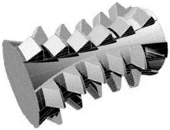
[0015] Taking the planar quadratic enveloping toroidal worm gear hob as an example, the relevant parameters are: the center distance of the toroidal worm pair a = 175mm, the hob tooth root arc radius R f0 =152.4mm, hob addendum arc radius R a0 =158mm, number of rows of cutter teeth N z = 6, the chip flutes are straight grooves, uniformly distributed in the circumferential direction, and the included angle of each rake face is 60°, and the rake face of a row of cutter teeth passes through the tooth thickness point of the hob throat. The hob has a total of 31 teeth, the relief angle of the teeth is χ=5°, and the width of the blade is l E =1mm, knife tooth thickness η=15mm.

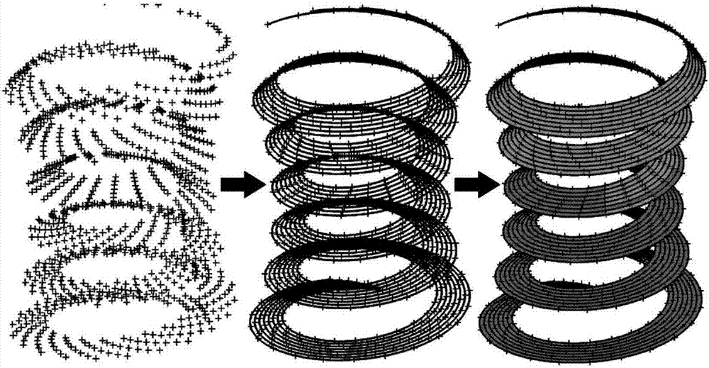
[0016] figure 2 Shown is a schematic diagram of the distribution of point families on the contour surface of the toroidal worm gear hob. Using the helicoid forming principle of the toroidal worm ...


PUM


Abstract

The invention relates to a ring surface worm gear hob CAD/CAM method based on a four-axis or more-then-four-axis linkage general CNC milling machine, and belongs to a designing and manufacturing method of a ring surface worm gear hob. By utilization of the ring surface worm gear hob spiral face and side rear angular face forming principle, point families evenly distributed on the spiral faces on the left and right sides of the hob, the left and right edge strip terminated lines and the left and right side rear angular faces are obtained; the point families are imported into three-dimension software to be fit into the spiral faces on the left and right sides of the hob, the left and right edge strip terminated lines and the left and right side rear angular faces; a remaining curved face structure is built through the simple feature command according to parameters, and a complete ring surface worm gear hob three-dimension model is obtained; and the model is imported into a four-axis or more-then-four-axis linkage general CNC milling machine system, and automatic machining of the hob is achieved only through the three procedures of rough milling, heat treatment and fine milling. The hob machining process is simplified, and the hob manufacturing precision is improved.

Description

technical field [0001] The invention relates to a CAD / CAM method for a toroidal worm gear hob based on a universal numerically controlled milling machine linked by four or more axes, and belongs to the design and manufacturing method of a toroidal worm gear hob. Background technique [0002] Compared with the cylindrical worm drive, the toroidal worm drive has strong bearing capacity, small size, high transmission efficiency and long service life, and is widely used in high-efficiency and heavy-duty occasions. However, the meshing theory of the toroidal worm drive is complex, and the meshing transmission performance is very sensitive to errors and deformations, requiring high-precision manufacturing. However, the toroidal worm gear hob used in the machining of the toroidal worm gear is a special tool with complex structure and great difficulty in design and manufacture. The processing process of the existing integral toroidal worm gear hob is cumbersome, and it is necessary...

Claims


Application Information

Patent Timeline
IPC IPC(8): B23C3/00G06F17/50
CPCB23C3/00G06F30/17G06F30/20
Inventor 李海涛龙新佳妮魏文军芮成杰杨杰
Owner CHINA AGRI UNIV
Why Eureka
Try Eureka