Nondestructive testing method for residual stress of sample surface

A technology of residual stress and sample groove, which is applied in the direction of measuring device, using sound wave/ultrasonic wave/infrasonic wave to analyze solids, and using sound wave/ultrasonic wave/infrasonic wave to analyze materials, etc. Quantitative results and other issues to achieve the effect of saving operating time and improving accuracy

Inactive Publication Date: 2017-11-07
EAST CHINA UNIV OF SCI & TECH
View PDF4 Cites 15 Cited by
  • Summary
  • Abstract
  • Description
  • Claims
  • Application Information

AI Technical Summary

Problems solved by technology

[0008] However, this method has certain limitations: (1) This method mostly uses the "one send, one receive" or "one send, two receive" type, and the measured results are often the average value in the acoustic channel, which makes it difficult to measure local areas (2) This method is a contact measurement method, which can only be applied to the measurement of plane surface residual stress, but for a wide variety of metal components, especially for complex structures or curved surface components such as aeroengine blades, It is difficult to obtain qualitative and quantitative results by applying traditional residual stress detection methods

Method used


Image

  • Nondestructive testing method for residual stress of sample surface
  • Nondestructive testing method for residual stress of sample surface
  • Nondestructive testing method for residual stress of sample surface

Examples


Embodiment Construction

[0033] Below, in conjunction with the accompanying drawings, preferred embodiments of the present invention are given and described in detail, so that the functions and features of the present invention can be better understood.

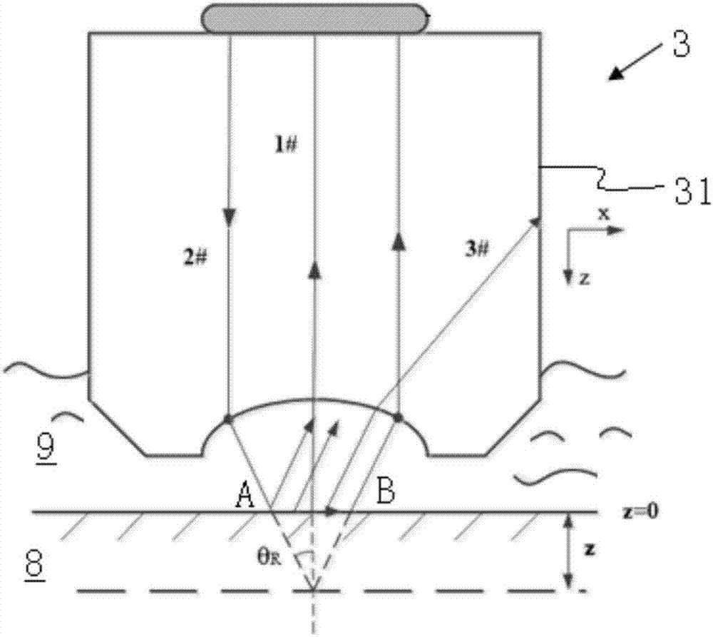
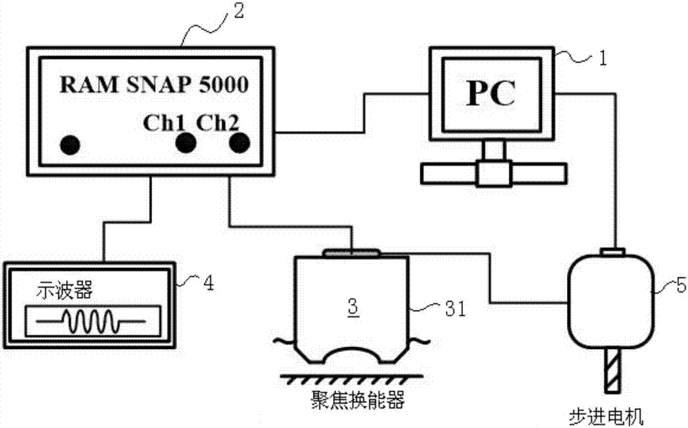
[0034] image 3 with Figure 4 An ultrasonic surface wave sound velocity measurement system according to one embodiment of the present invention is shown. Such as image 3 Shown is the circuit diagram of the ultrasonic surface wave sound velocity measurement system, the ultrasonic surface wave sound velocity measurement system includes an ultrasonic measurement device 2, the ultrasonic measurement device 2 is connected with a single-chip microcomputer 1 and an oscilloscope 4, and the ultrasonic measurement device 2 is switched to a focus The transducer 3 supplies power, receives the signal of the ultrasonic probe 31 of the focusing transducer 3, and sends the signal to the oscilloscope 4. In addition, the ultrasonic surface wave sound velocity mea...


PUM


Abstract

The invention provides an ultrasonic surface wave velocity measurement system, which comprises an ultrasonic testing device connected with a control device and an oscilloscope separately, wherein the ultrasonic testing device is used for providing a focused transducer of which a probe is vertically downward with electricity, receiving a signal of the ultrasonic probe of the focused transducer and transmitting the signal to the oscilloscope; a sample cell is also arranged at the lower part of the focused transducer; the sample cell containing a liquid; the ultrasonic probe of the focused transducer is immersed into the liquid; and a drive mechanism is fixed on the sample cell and connected with the focused transducer. Only the ultrasonic surface wave velocity of an area of propagating an ultrasonic surface wave, namely the area opposite to the focused transducer is measured, and the propagation distance of the excited ultrasonic surface wave in the material is very small, so that detection of the residual stress of a local area is achieved; and the surface wave is excited by adopting the noncontact focused transducer, so that the residual stress of the surface of a curve structure can be measured, thereby achieving measurement of the residual stress of the curve structure.

Description

technical field [0001] The invention relates to a detection method of residual stress, in particular to a non-destructive detection method of surface residual stress. Background technique [0002] Residual stress is the stress that exists inside the object in an equilibrium state under the action of external force, and is sometimes called internal stress or locking stress. Changes in ambient temperature or mechanical processes such as rolling, forging, welding, etc. cause local plastic deformation of the material, resulting in residual stress. [0003] In industrial production, the process performance and service life of metal parts are often closely related to the residual stress inside the metal material. During the service process of the component, due to the superposition of residual stress and external load, the component will produce secondary deformation. This local uneven elastic-plastic deformation will change the material lattice, resulting in the redistribution o...

Claims


Application Information

Patent Timeline
Patent Type & Authority Applications(China)
IPC IPC(8): G01N29/07G01N29/24
CPCG01N29/07G01N29/24
Inventor 项延训轩福贞涂善东刘长军李昀泽
Owner EAST CHINA UNIV OF SCI & TECH
Why Eureka
Try Eureka