
Reducing pipe fitting

A technology of pipe fittings and pipes with different diameters, which is applied in the field of pipe fittings with different diameters. It can solve the problems of affecting normal use, poor heat preservation effect, and freezing of water in water pipes, and achieves the effects of easy manufacture, high connection strength and reliable sealing.

Inactive Publication Date: 2017-11-10
弘毅天承知识产权股份有限公司
View PDF0 Cites 0 Cited by
  • Summary
  • Abstract
  • Description
  • Claims
  • Application Information

AI Technical Summary

Problems solved by technology

[0005] The insulation effect of the existing pipeline water supply pipeline is poor, and it is easy to cause the water in the water pipe to freeze in winter or in a cold environment, affecting normal use

Method used


Image

  • Reducing pipe fitting
  • Reducing pipe fitting

Examples


Embodiment 1

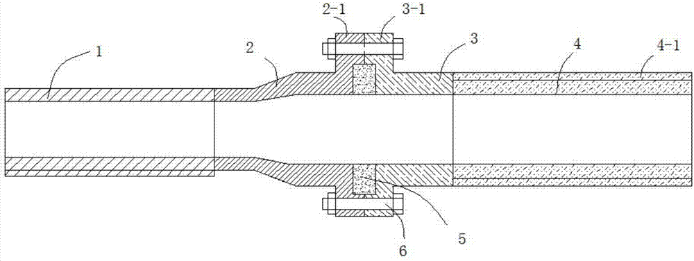
[0021] Such as Figures 1 to 2 As shown, this embodiment provides a pipe fitting with a different diameter, including a small-diameter pipe 1 at the left end and a large-diameter pipe 4 at the right end. 2. The diameter of the right end of the reducing joint 2 is the same as that of the large-diameter pipe 4, and the left end of the large-diameter pipe 4 is welded with a joint 2 3 having the same diameter as the large-diameter pipe 4, and the reducing joint 2 and the joint 3 are respectively provided with Flange A2-1 and flange B3-1 that cooperate with each other, the surfaces of flange A2-1 and flange B3-1 are provided with annular anti-corrosion grooves, and the annular anti-corrosion grooves of flange A2-1 and flange B3-1 The grooves form an anti-corrosion cavity, and the anti-corrosion cavity is provided with an annular anti-corrosion inner lining 5, 4 sets of large-diameter pipes are provided with an insulation layer 4-1, and the outer wall of the small-diameter pipe 1 is...

Embodiment 2

[0024] This embodiment is further optimized on the basis of embodiment 1, specifically:

[0025] The thermal insulation layer 4-1 includes multiple layers of glass fiber layers and multiple layers of aluminum foil stacked in sequence, and two adjacent layers of aluminum foil layers are not in contact.

[0026] The inner walls of the small-diameter pipe 1 and the large-diameter pipe 4 are coated with an epoxy anti-corrosion layer, and the material of the annular anti-corrosion lining 5 is a polytetrafluoroethylene layer 6-2.

Embodiment 3

[0028] This embodiment is done as follows on the basis of any of the above embodiments

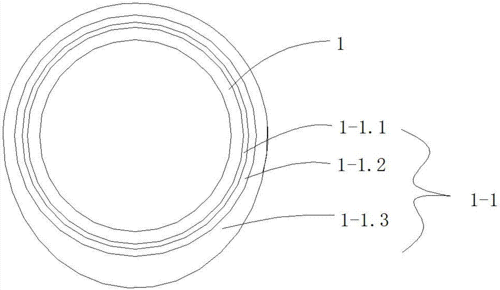
[0029] The composite anticorrosion layer 1-1 includes a primer layer 1-1, an aluminum silicate wool layer 1-2 and an anticorrosion layer 1-3 coated on the outer wall of the small-diameter pipe 1 in sequence, and the top of the aluminum silicate wool layer 1-2 is The thickness of the wrapped anti-corrosion layer 1-2 is smaller than the thickness of the anti-corrosion layer wrapped at the bottom of the aluminum silicate cotton layer 1-2.

[0030] The anti-corrosion layer 1-3 is a polyester anti-corrosion layer.

[0031] The flange A2-1 and the flange B3-1 are fixed by a plurality of evenly distributed bolt assemblies.


PUM


Abstract

The invention discloses a different-diameter pipe fitting, which relates to the technical field of pipelines. The invention includes a small-diameter pipe at the left end and a large-diameter pipe at the right end. The diameter of the right end of the joint is the same as that of the large-diameter pipe, and the left end of the large-diameter pipe is welded with a joint 2 with the same diameter as the large-diameter pipe. The different-diameter joint and joint 2 are respectively provided with flanges A and flanges that can cooperate with each other. B. The surfaces of flange A and flange B are both provided with annular anti-corrosion grooves, and the annular anti-corrosion grooves of flange A and flange B form an anti-corrosion chamber. The anti-corrosion chamber is provided with a ring-shaped anti-corrosion lining. The outer wall of the large-diameter pipe The upper sleeve is provided with an insulating layer, and the outer wall of the small-diameter pipe is provided with a composite anti-corrosion layer. The invention has the advantages of simple structure, reliable connection of different-diameter pipes, and good anti-corrosion and heat preservation effects for both large-diameter pipes and small-diameter pipes.

Description

technical field [0001] The invention relates to the technical field of pipelines, and more specifically relates to a pipe fitting with a different diameter. Background technique [0002] The sewage treatment equipment is connected by pipes. There are three types of existing pipes: the first type is metal pipes, the second type is plastic composite metal pipes, and the third type is plastic pipes. [0003] However, the corrosion problem of the existing metal water supply pipelines affects the service life of the pipelines, so the inner walls of the pipelines are generally coated with anti-corrosion coatings and other anti-corrosion treatments. During the welding process of the pipe connection, the pipe wall is heated to damage the anti-corrosion layer, which affects the anti-corrosion performance, and causes the joints of the pipe to be corroded and leak. [0004] Existing anti-corrosion pipelines generally implement anti-corrosion by adding an anti-corrosion layer on the ou...

Claims


Application Information

Patent Timeline
Patent Type & Authority Applications(China)
IPC IPC(8): F16L23/032F16L58/02F16L59/02
CPCF16L23/032F16L58/02F16L59/02
Inventor 樊明伟
Owner 弘毅天承知识产权股份有限公司
Learn More