Microfluidic reactor, application thereof, detection system and method for detecting liquid phase interface ion distribution

A reactor and microfluidic technology, applied in the field of high vacuum system, can solve the problems that affect the vacuum degree of the main vacuum chamber and cannot be detected, and achieve the effects of low cost, detection and simple production

Inactive Publication Date: 2017-11-14
INST OF CHEM CHINESE ACAD OF SCI
View PDF4 Cites 4 Cited by
  • Summary
  • Abstract
  • Description
  • Claims
  • Application Information

AI Technical Summary

Problems solved by technology

[0003] However, technologies such as ToF-SIMS, XPS, and SEM all need to be implemented based on vacuum, but the vapor pressure of water at room temperature is about 20kPa, so it is easy to be ejected in the vacuum, thus affecting the vacuum degree of the main vacuum chamber, and will not be able to Therefore, the sample to be tested must be a solid that is compatible with vacuum. At present, it is a huge challenge to apply this kind of technology to the detection of liquid phase interface.

Method used


Image

  • Microfluidic reactor, application thereof, detection system and method for detecting liquid phase interface ion distribution
  • Microfluidic reactor, application thereof, detection system and method for detecting liquid phase interface ion distribution
  • Microfluidic reactor, application thereof, detection system and method for detecting liquid phase interface ion distribution

Examples


Embodiment 1

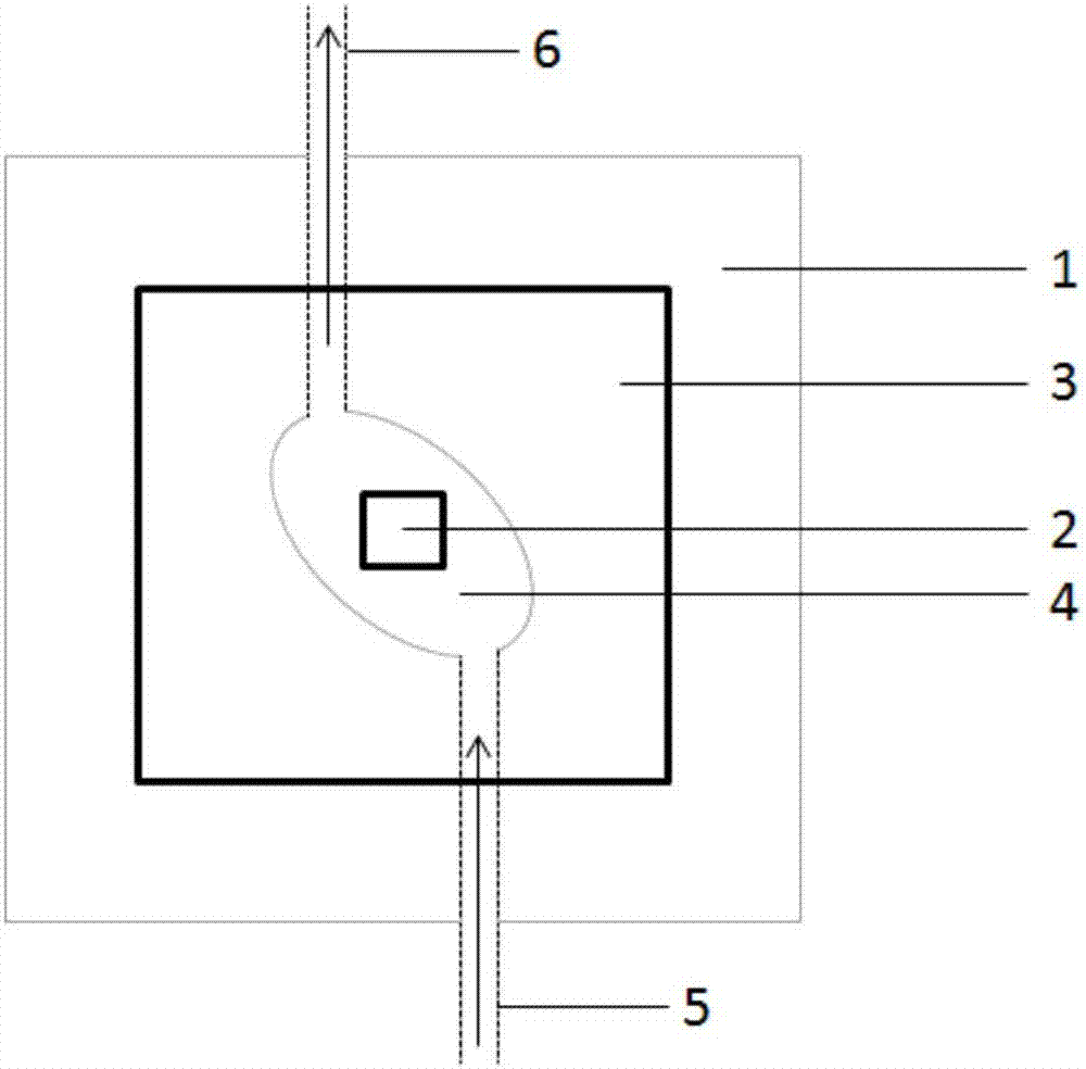
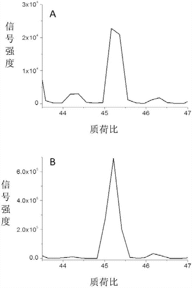
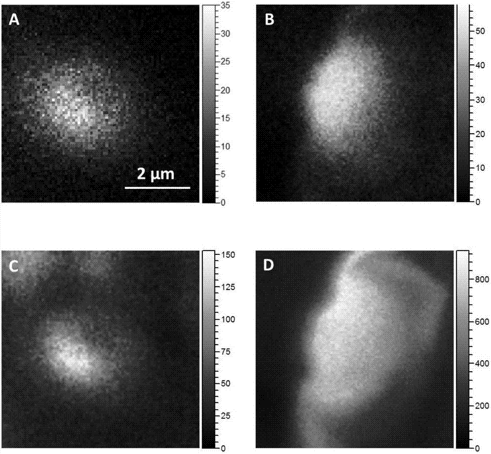
[0040] Fill the microfluidic reactor with diluted ethanol from one side of the pipeline at a peristaltic pump flow rate of 10 μL / s through a syringe, seal the pipeline with a PEEK plug, and fix the microfluidic reactor on the ToF-SIMS sample plate Put it into the sampling chamber after putting it on, and after evacuating for 30 minutes, the vacuum degree of the sampling chamber is 1×10 -6 mbar, then transfer the reactor to the main vacuum chamber (vacuum degree is 1×10 -7 mbar), and use a primary ion beam (200nm in diameter) to bombard the silicon nitride film (2μm in diameter), and its vacuum degree is still 6×10 -7 mbar (indicating that the microfluidic reactor has good vacuum compatibility), and then detect the secondary ions in ToF-SIMS positive ion mode, the obtained mass spectrum is as follows figure 2 Shown in A; and then perform mass spectrometry imaging of positive and negative ions in the 6 μm region, and the two-dimensional imaging diagrams of the secondary ions a...

Embodiment 2

[0042] Fill the microfluidic reactor with diluted formic acid from one side of the pipeline at a peristaltic pump flow rate of 10 μL / s through a syringe, seal the pipeline with a PEEK plug, and fix the microfluidic reactor on the ToF-SIMS sample plate Put it in the sampling chamber after putting it on, and after evacuating for 30 minutes, the vacuum degree of the sampling chamber is 2×10 -6 mbar, then transfer the reactor to the main vacuum chamber (vacuum degree is 1×10 -7 mbar), and use a primary ion beam (250nm in diameter) to bombard the silicon nitride film (3μm in diameter), and the vacuum degree of the main vacuum chamber is still 8×10 -7 mbar (indicating that the microfluidic reactor has good vacuum compatibility), and then detect the secondary ions in ToF-SIMS negative ion mode, the obtained mass spectrum is as follows figure 2 As shown in B; and then perform mass spectrometry imaging of positive and negative ions in the region of 6 μm, the two-dimensional imaging d...


PUM

PropertyMeasurementUnit
areaaaaaaaaaaa
thicknessaaaaaaaaaa
areaaaaaaaaaaa

Abstract

The invention relates to the field of high vacuum systems and discloses a microfluidic reactor, application thereof, a detection system and a method for detecting liquid phase interface ion distribution. The microfluidic reactor comprises a substrate and a silicon wafer, wherein a part of the silicon wafer is replaced by a silicon nitride membrane, the substrate has a concave structure for accommodating a sample, the concave structure is completely covered by the silicon wafer, the silicon wafer and the concave structure can jointly forms a sealed sample base, an the area replaced by the silicon nitride membrane is arranged above the concave structure, and the size of the area replaced by the silicon nitride membrane is smaller than or equal to the upper surface area of the concave structure. The invention further discloses application of the microfluidic reactor in detecting the liquid phase interface ion distribution. The detection system comprises the microfluidic reactor and a flight time secondary ion mass spectrometer. The method for detecting the liquid phase interface comprises the step of putting the microfluidic reactor where liquid to be detected is arranged into the flight time secondary ion mass spectrometer to befor being analyzed. The microfluidic reactor disclosed by the invention can achieve detection of the liquid phase interface in vacuum.

Description

technical field [0001] The present invention relates to the field of high-vacuum systems, in particular to a microfluidic reactor and its application, more specifically to a microfluidic reactor and its application, a detection system, and a method for detecting ion distribution at a liquid phase interface . Background technique [0002] The gas-liquid interface chemistry and solid-liquid interface chemistry of water phase are very important for environmental science, biology and industrial development, but their analysis and detection are difficult to carry out. Studies have shown that interface chemistry is very different from bulk chemistry. For example, people have simulated the distribution of halogens in NaF, NaCl, NaBr and NaI solutions at the interface and in the bulk phase by computer. The results show that F - , Cl - Mainly distributed in the bulk phase, while Br - , I - There will be different degrees of enrichment at the interface, but this result has not bee...

Claims


Application Information

Patent Timeline
Patent Type & Authority Applications(China)
IPC IPC(8): G01N27/62B01J19/00
CPCG01N27/62B01J19/0093B01J2219/00786
Inventor 汪福意王朝英罗群吴魁
Owner INST OF CHEM CHINESE ACAD OF SCI
Why Eureka
Try Eureka